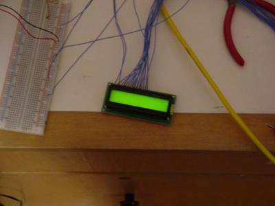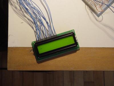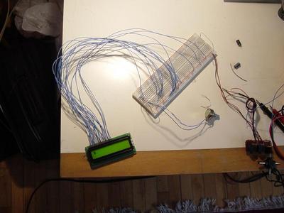
The Backlight Works
I started by connecting the pins 15, and 16 to VCC and GND for power for the
display's backlight.
Pin's 1 and 2 were connected to GND and VCC to power the display. Pin 3 was
connected to a 10k potentiameter between VCC and GND to adjust the contrast
of the display.
Pin 5 was connected to GND to indicate the display will be in write mode.
Pin 4 was connected to pin 17 of the parallel port to control the operation
mode of the display. A high is data mode, and a low signal is operation mode.
Pin 6 was connected to pin 1 of the parallel port to control the read/write
enable.
Pins 7 through 14 were connected to pins 2 through 9 on the parallel port for
the data signal. Pins 18 through 25 are GND on the parallel port.
Initially I couldn't get the LCD display to work, so I tested it by hardwiring
the data lines, the operation mode bit, and the read write enable bit.
My first step was to test the instruction mode. I conected data pins 0 through
3 to VCC and 4 through 7 to GND to represent the number 15, which is the instruction
to turn the cursor on. The operation mode bit was connected to GND to indicate
instruction mode. After some experimenting I figured out that the read write
enable bit had to be alternated between VCC and GND to accept an operation.
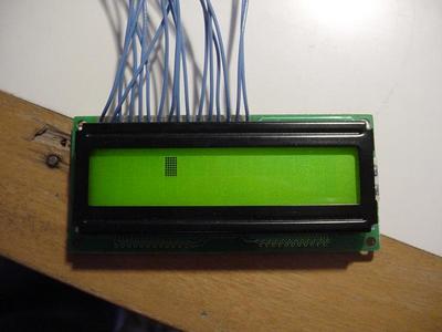
My operation worked and the cursor was enabled.
To test the data mode I left the data lines wired to 15, which is the space
character in ascii. The operation mode bit was connected to VCC to set the display
to data entry mode. Alternating the read write enable between VCC and GND produced
successive space characters on the display.

I hadwired the display. This is the instruction to turn the cursor on.

Now I want to test the data entry.

I hardwired the space character as input