Video Clips

Axi-vision Camera and 3D Television

In collaboration with the NHK team, Iizuka's team invented the Axi-Vision Camera, which is a 3D television camera that can capture depth images simultaneously with the color image. Click the demo buttons to view various effects created by means of the Axi-Vision Camera.

pop can lady and screen revolving planets

For further details please refer to the electronic online journal Optics Express of the Optical Society of America http://www.opticsexpress.org/abstract.cfm?URI=OPEX-12-12-2781


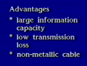
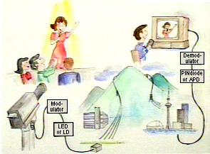
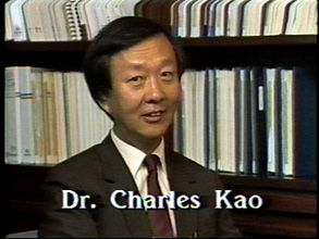
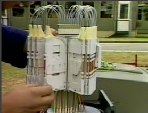
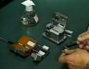
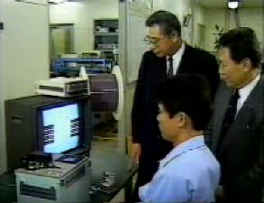
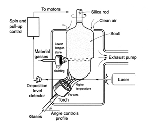
Fiber Optic Labs from Around the World

Iizuka produced "Fiber Optics Labs from Around the World," an educational video sponsored by IEEE, to give viewers the opportunity to visit word renowned research centers and explore the latest developments in fiber optics. Click the buttons in the sections below to view segments from this video, posted with permission from IEEE.

Fiber Optics Labs from Around the World


Advantages of optical fibers

Narrator: The advantages of optical fiber over copper wire are many. Because the frequency of light is several orders of magnitude larger than microwave frequencies, the information capacity is also several orders of magnitude larger. Huge bundles of copper wire can be replaced by a single optical fiber. Low transmission loss means a larger span between repeaters, typically several tens of kilometers. Since the glass fiber is non-metallic, it does not suffer from electromagnetic noise problems. Heavy shielding metals are not necessary, and the glass fiber cable is substantially lighter than its metal counterpart.

Components in a typical fiber optic communication system

Narrator: Here we see a typical optical communication system. Image and voice data are recorded by the video camera. This data is in the form of an electrical signal, which is modulated and used to drive a light source such as a laser diode or light emitting diode. The light source converts the modulated electrical signal into a modulated light signal. The light signal is coupled into an optical fiber where it may travel thousands of kilometers to its destination. On the way, the light signal may also pass through various routing and signal processing devices, such as optical couplers, switches, multiplexers, and amplifiers. At the destination, a photodector converts the light signal back into an electrical signal, where in this case, it is demodulated for viewing on a home TV screen.


First stop on the fiber optics tour

Narrator: Our first visit is with Dr. Charles Kao. Dr. Kao's historic paper, "Dielectric fibre surface waveguides for optical frequencies" published in 1966 set the stage for fiber optic development. Because of this historic paper, Dr. Kao is often referred to as the father of fiber optic communication.

Challenges faced in the early days

Dr. Kao: We were in a way lucky to, first of all, find that there are solid samples that have low loss, and also that the techniques that we later developed for measurement were sufficiently sensitive to produce those two curves that you saw in the paper. In all these sorts of projects, one has to convince the people that fund these projects that it is a real project. And so when the light source cannot work at greater than liquid nitrogen temperature, which is 77 degree Kelvin, and the loss, which is one thousand times in dBs too high, it was extremely difficult to sell that project at that time.


British Telecom

Dr. Iizuka: Today I am visiting British Telecom Research Laboratories in Ipswich, some 60 miles northeast of London. This laboratory covers such research areas as radio, mobile radio, microwave, and optical communication systems. The first group was directed by Dr. Midwinter. Since then, this laboratory has enjoyed a prestigious position in field of optics. They were the first to employ single mode fiber in extensive use in trunk lines.

Fiber to the home

Narrator: We are only just beginning to tap the tremendous potential of the optical fiber. Bringing fiber to the home is the next big step in realizing this potential.
Dr. Peter Cochrane: Today, optical fiber is providing about half the global communication capacity for long line transmission. We are now progressing down networks toward customers. Fiber to the home has got to be the next big goal.
Narrator: So how can this goal be achieved, not only cost effectively, but also in a way that will cope with the new and unexpected demands of the future? At BT Research Labs, the careful planning and development necessary for a largely transparent network is well underway. There is already a new system under development, which will make fiber to the home a realistic proposition. This will be achieved by sharing fiber access between customers. It's possible to take the light from a single customer and combine it together with the light of many other customers and feed that light back on a single fiber into the telephone exchange. Equally, light from the telephone exchange can be fed out on a single fiber and split between many customers.


Nippon Electric Company (NEC)

Narrator: Our next stop is Nippon Electric Company in Japan. We will be talking to Dr. Uchida who is best known for developing the SELFOC fiber.
Dr. Iizuka: Dr. Uchida, thank you very much for your invitation today.
Dr. Uchida: Very nice to meet you again, Professor Iizuka.

Optical CATV transmitter

Narrator: The first laser diode is modulated by the channel 1 TV signal. The second laser diode is modulated by the channel 2 TV signal. And likewise for the remaining channels. The frequency interval between laser diode channels is 8 GHz. The ten input channels are scrambled in the 16x16 star coupler. Each output fiber from the coupler contains a portion of the signal from all ten input fibers. The automatic frequency control unit contains a tunable laser whose frequency is swept as shown. Part of the signal from the swept laser is mixed with the ten input frequencies supplied by an output fiber from the star coupler. Beat pulses are produced. The beat pulses are compared with reference pulses obtained by feeding the swept laser signal into a Fabry–Pérot resonator. Comparing the signals, any difference in time equates to a difference in frequency and is used to correct the input laser diode frequency. An advantage of this system is that absolute frequency need not be controlled, only the frequency interval.

Optical heterodyne receiver: explanation

Narrator: In this scheme, wavelength filters are not required for channel selection. Rather, channel selection involves tuning a local oscillator laser diode to a frequency near that of the desired TV channel. The local oscillator frequency is optically mixed with the light from the transmission line. The resulting intermediate frequency is amplified and fed into the home TV screen for viewing.

Optical heterodyne receiver: demonstration

Dr. Uchida : Now, this indeed shows one program. Now, I am going to switch on another channel. Like this, we can easily select our desired channel.


Sumitomo

Narrator: Our final stop is Sumitomo Electric where we will be talking with Dr. Nakahara. The tour of Sumitomo's facilities gives us the chance to see fiber optic communication from the production point of view.

Mass fusion splicing: fiber preparation

A technician prepares a four fiber tape for fusion splicing. The preparation steps demonstrated in this video clip are as follows:
(a) The fibers are placed in a positioner.
(b) The plastic coating is stripped off.
(c) The stripped fibers are cleaned.
(d) The cleaned fibers are placed in a cleaving tool. The technician slides a blade across the underside of the fibers, which scores the fibers.
(e) The scored fibers are cleaved by pressing down on the arm of the cleaving tool. The cleaved fibers are removed from the cleaving tool and are now ready to be placed in the mass fusion splicing machine.


Mass fusion splicing: demonstration

Dr. Nakahara and Dr. Iizuka observe as a technician splices the prepared four fiber tapes. The fusion splicing steps demonstrated in this video clip are as follows:
(a) The fibers are placed in the splicing jig. For demonstration purposes, the entire process is monitored on a TV screen.
(b) The fibers are brought together, and the machine checks the vertical and horizontal positions, making adjustments if necessary.
(c) The fibers are fused by an arc discharge.
(d) The fiber vertical and horizontal positions are checked after the fusion, and the machine calculates the splice loss for each splice, typically well below 0.1dB
.

Vapor-Phase Axial Deposition (VAD)

Narrator: In this diagram, we see how the preform is made. A seed rod is slowly rotated and pulled upward. As the seed rod is pulled, two burners deposit fine glass soot. The lower burner in this diagram is depositing the core glass material, and above it is a burner depositing the cladding glass. The rate at which the seed rod is pulled is carefully controlled by servo mechanisms. After deposition the glass soot rod is dehydrated and sintered into a solid preform in a furnace.

home