Using cellophane to convert a liquid crystal display screen into a three
dimensional display (3D laptop computer and 3D camera phone)
Keigo lizuka
Department of Electrical & Computer Engineering
35 St. George Street
University of Toronto
Toronto, Ontario, Canada M5S 1A4
Contents
Abstract
1. Properties of Cellophane
2. Stereoscopic Principles
3. Manipulating Polarized Light
4. Creating 3D Images
5. Eye Fatigue
6. Eliminating the Need to Wear Glasses
7. Using a single camera phone
8. Method Summary
9. New Applications
10. Conclusion
References
Abstract
We present a novel, inexpensive, stereoscopic technique for generating 3D images
from cellophane on a liquid crystal displays which are most typically used for
a laptop screen or a camera phone screen. Stereoscopy requires independent manipulation
of the left and right eye views. 1 Our technique takes advantage
of two facts; the first is that the light from the liquid crystal display of
either a laptop computer or a camera phone is polarized light 2,
and therefore we can easily manipulate its transmission with a polarizer sheet.
The second fact is that a cellophane half-waveplate can change the direction
of polarization of light. The direction of polarization of one half of the liquid
crystal screen was rotated by the cellophane half-waveplate. Two images displayed
with orthogonal polarization on two halves of the screen become separable by
wearing a pair of glasses of orthogonal polarization.
A distinct advantage of our technique is its simplicity; either a laptop screen
or a camera phone screen can be converted into a 3D display with minimal knowledge
of optics. An additional advantage of our technique is that we can eliminate
the need for the observer to wear special glasses by making the screen wear
the glasses instead. This is possible because there is normally only one viewer
at a time, and the relative orientation of the viewer's head and the screen
is sufficiently stationary. A further significant discovery is that we verified
that cellophane (costing mere pennies) proved to be a better half-waveplate
than a commercial half-waveplate (costing hundreds of dollars for the required
size) for rotating the polarization of white light.
1. Properties of cellophane
Let us begin by examining the properties of cellophane. Cellophane is fabricated
by protruding an alkaline viscose solution through a narrow die into an acid
bath. Because of the unidirectional strain during the protruding process, cellophane
is an anisotropic material and it behaves like a calcite crystal. The refractive
index ny of cellophane measured by a light wave component polarized
in the direction of the longer dimension of the rolled cellophane (in the y
direction) is larger than nx, measured by a light wave component
polarized in the direction of the shorter dimension (in the x direction).
As a result, the component polarized in the x direction propagates through
the medium faster than the component polarized in the y direction. After transmission
through such a medium, a phase difference arises between these two light wave
components. The difference ny-nx in the refractive index
and the thickness of the cellophane determine the amount of the phase difference
between the components polarized in the x and y directions. A medium that creates
a 180o phase delay is a half-waveplate. The phase difference incurred
in our plain ordinary colorless cellophane sample was measured to be 170.2o
, which is about 95% of the phase delay of an ideal half-waveplate. Our cellophane
sample was purchased from Lewiscraft.
It was sold under the brand name "cello GIFT WRAP clear," and its
SKU number was listed as #17606. We measured the cellophane thickness to be
25 microns. The 170.2o phase delay of is within acceptable limits
for a number of practical applications that do not require a precise 180o
phase delay. (For an unknown kind of cellophane, a simple test
can be performed by inserting the cellophane in question between two polarizer
sheets polarized in the same direction. As you rotate the cellophane sheet you
may see a variation in the transmittance of the polarizer sheets. If you can
find an angle for which the polarized sheets become almost completely opaque,
the cellophane passes the test. If there is no angle for which the sheets become
opaque, the cellophane sheet is of no use. There are two very important tests
that need to be done in order to construct your 3D system. This is the first
important test, which is confirming that the cellophane has the necessary properties.
The second test, which confirms the the crisscrossed paths, is explained later).
One of the most important functions of a half-waveplate is its ability to rotate
the direction of polarization of the transmitted light. We found that cellophane’s
performance in rotating the direction of polarization of white light was superior
to that of a commercially available half-waveplate designed for a specific wavelength.
An added bonus is that cellophane is very inexpensive. Before describing the
role of a half-waveplate in generating 3D images, we need to introduce some
basic stereoscopic principles.
2. Stereoscopic principles
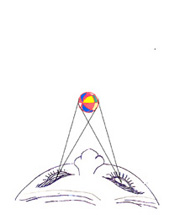
Figure 1 explains the basic principle of a 3D display based upon the parallax
effect1.
|
|
|
|
(a)
|
(b)
|
The observer sees the ball in front of his or
her eyes.
|
A picture of the ball is drawn on the screen by
extending the lines from the eyes to the ball.
|
|
|
|
|
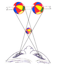
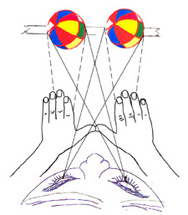
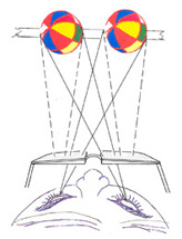
(c)
|
(d)
|
The observer sees two balls on the screen, and there
is no stereoscopic effect as yet. To produce a stereoscopic effect,
we must find a way to eliminate the views represented by the dashed
lines. The simplest although not the most practical way is to block
the dashed line paths by extended hands.
|
For a more practical method, polarized light is
used. Polarizer glasses are worn to block the dashed line paths
yet pass the solid line paths.
|
Fig. 1
Principle of stereoscopy.
|
|
Figure 1(a) shows what an observer’s left and right eyes see when a Fusen (a
traditional Japanese ball) is flying toward the observer. The left eye sees
the ball to its right, while the right eye sees the same object to its left.
Our brain judges the distance to the ball using this information as well as
other factors. Figure 1(b) is an attempt to fool the brain. Two pictures of
the ball are drawn on the screen located behind the ball by extending the lines
of sight onto the screen. As far as the light paths between the center-crossing
point and both eyes are concerned, they are the same as the light path that
would have been created by the actual ball.
Do these two ball pictures on the back screen alone give the observer the illusion
that the ball exists off the screen? The answer is emphatically "No!" The reason
is that each eye sees both pictures of the ball on the screen as indicated by
the solid-line traces and the dashed-line traces in Fig. 1(c). In order to create
the illusion that the ball exists off the screen, we must find a way to ensure
that each eye sees only one picture of the ball as indicated by the solid-line
traces blocking the dashed-line traces. Try to block only the dashed-line traces
and pass the solid-line traces by extending your hands. You will find the picture
becomes instantly three dimensional. If we eliminate the pictures that correspond
to the dashed-line traces in Fig. 1(c), the light paths in Fig. 1(c) become
identical to the light paths shown in Fig. 1(b), and the illusion that the ball
exists outside the screen is created. One way to accomplish this without using
hands is by using polarized light and wearing polarizer glasses as shown in
Fig. 1(d). Manipulation of polarized light makes it possible for each eye to
see only the picture corresponding to the solid-line traces.
3. Manipulating polarized light
Polarized light is used not only because our eyes are insensitive to the polarization
of the light wave, but also because its path can be selectively blocked or transmitted
by using a polarizer. If the polarizer's transmission axis is parallel to the
polarization direction of the incident light, the light passes through the polarizer
with minimum attenuation. On the other hand, if they are perpendicular to each
other, the light is absorbed by the polarizer and does not transmit through.
Now, we can take advantage of the fact that the light emanating from the liquid
crystal screen of a laptop computer or a camera phone is linearly polarized2.
The light from the liquid crystal display is linearly polarized simply because
the top surface of the liquid crystal screen is covered by a polarizer sheet
as one of the necessary parts of the liquid crystal display.
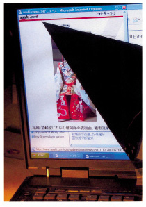
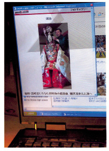
In Fig. 2, a triangular-shaped polarizer sheet is held up
to a laptop computer screen.
|
|
|
|
(a)
|
(b)
|
The transmission axis of the polarizer is perpendicular
to the direction of polarization of light from the screen.
|
The polarizer in (a) is rotated by 90°. The transmission
axis of the polarizer is now parallel to the direction of polarization
of light from the screen.
|
|
Fig. 2
A triangular-shaped polarizer sheet is held up to a laptop computer
screen.
|
|
In Fig. 2(a), the polarizer sheet is oriented with its transmission axis perpendicular
to the polarization direction of the light from the screen. With this orientation,
the polarizer sheet is quite effective at blocking the light from the screen.
In Fig. 2(b), the transmission axis of the polarizer sheet is rotated by 90°
so that it becomes parallel to the polarization direction of light from the
laptop screen. With this orientation, the polarizer sheet becomes transparent.
The same type of demonstration can be made using the screen of a camera phone.
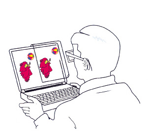
4. Creating 3D images
4.1 Using a laptop computer
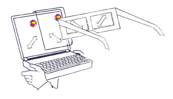
Figure 3 illustrates how we can obtain 3D images from the liquid crystal display
of a laptop computer3. The polarization directions are indicated
by double-headed arrows.
|
|
|
|
(a)
|
(b)
|
By wearing polarizer glasses, the observer sees only
the light paths represented by the solid lines in Fig. 1(c). The
polarizer glasses reject the light paths represented by the dashed
lines in Fig. 1(c).
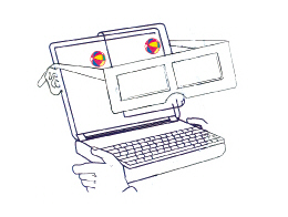
|
The laptop computer wears the polarizer glasses instead
of the observer.
|
|
Fig. 3
Converting a laptop computer screen into a 3D display.
|
|
The "polarizer" glasses shown in Fig. 3 are glasses in which the coverings
for the eyes are constructed from polarizer sheets that have been cut down to
a size suitable to fit into the cardboard frames of the glasses. With our laptop
computer, the direction of polarization of the light from the screen is at 45°
from the horizontal direction. (Note that the direction of polarization of light
is not necessarily at 45°; the angle depends on the
type and make of the device. If it is not at 45°
the difference should be accounted accordingly). An observer looking at this
screen through polarizer glasses whose transmission axes are at 45°
will be able to see the whole screen.
If, however, the right half of the laptop computer screen is covered by a cellophane
sheet, the direction of polarization of the covered section is redirected to
135° (= 45° + 90°
). Let us first consider what the observer sees through his or her right eye
while wearing the polarizer glasses. The transmission axis of the polarizer
covering the observer’s right eye is at 45° , which
means the right eye can no longer see the covered section of the screen. The
right eye can see only the uncovered left half of the screen. In short, with
this configuration, the right eye sees only the ball displayed in the left half
of the laptop computer screen.
Next, we turn our attention to what the observer sees through his or her left
eye. If the direction of the transmission axis of the polarizer covering the
left eye is set at 135° , the left eye sees only
the picture of the ball displayed in the right half of the laptop computer screen;
it cannot see the ball in the left half of the screen.
In summary, with this configuration of the laptop computer screen (half covered
by cellophane) and the orientation of the polarizers in the viewing glasses
(left polarizer at 135° and right polarizer at 45°
), we can eliminate the light paths in the dotted lines in Fig. 1(c) and duplicate
the desired crisscross light path shown in Fig. 1(b), thus generating the illusion
to the observer that there exists an actual ball.
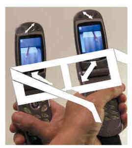
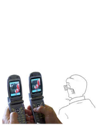
4.2 Using two camera phones
A similar experiment can be performed using two separate camera phones placed
side by side as shown in Fig. 4. (The details are reported in Ref. 4.) The two
camera phones are held with a spacing of about 6.5 cm, which is the average
spacing between human eyes. A pair of pictures taken with this spacing is a
pair of stereoscopic images. The object was a horizontally placed red pencil
tip pointing toward the cameraman. This stereoscopic pair is sent by the transmitter
phones to a pair of dialed distant receiver phones so that the two transmitted
images are reproduced at the receiver site.
The receiver site has to do two things:
- Transpose the images. To transpose the images, the image taken by the left
transmitting camera phone is sent to the right receiver phone, and likewise,
the image taken by the right transmitting camera phone is sent to the left
receiver phone. Otherwise, the tip of the reconstructed pencil image would
point away from the observer and the depth information would be reversed (pseudoscopic
image). The operation of the transpose is photographically indicated by the
crossed arms in Fig. 4(b).
|
|
|
|
(a)
|
(b)
|
Geometry.
|
Corresponding photograph.
|
|
Fig. 4
Viewing the transposed stereoscopic image in the receiver phones
through polarizer glasses.
|
|
- Rotate the polarization direction of one of the images. The display of the
left camera phone in Fig. 4 is covered with the cellophane half-waveplate
with its fast axis (the direction perpendicular to that of the roll of the
cellophane) in either the horizontal or vertical direction. Light from the
Panasonic GD 88 display is polarized at 135° from
the horizontal direction, while that of the cellophane-covered receiver phone
is now rotated by -90° to 45°
from the horizontal direction. Thus, the stereoscopic pair of images is displayed
with orthogonal polarizations on the two phones side by side. Images in orthogonal
polarization (135° on the right and 45°
on the left) become separable by wearing the above mentioned pair of glasses
of orthogonal polarization.
(Note that the direction of polarization of light from the laptop was 45°
whereas that of the camera phone is 135° and the
cellophane sheet was placed on the left phone so that the same pair of glasses
can be used for both the laptop and the camera phone). A sure
check is to examine whether or not the right eye can see only the screen of
the left phone, and similarly, the left eye can see only the screen of the
right phone, thus generating the illusion to the observer that there exists
an actual object off screen. (This is the second of the two most important
tests in constructing the 3D display system. The first test was to verify
the cellophane properties. The second test is to confirm
these crisscrossed light paths by using your hand to cover one eye at a time.)
5. Eye Fatigue
We now consider a modification to the configuration in order to ease the problem
of eye fatigue. We begin by reviewing factors that contribute to eye fatigue.
The eye ball itself rotates when viewing an object. The inside muscle (medial
rectus muscle) contracts and the outside muscle (lateral rectus muscle) expands
to turn the eyeball inward. The macula (yellow spot) near the optical axis is
the area where the sharpest image is formed in our retina, but it is tiny and
is within 4 degrees of the optical axis. The eye ball is continuously working
to place the image onto this spot. This eyeball movement is called convergence
or simply vergence to the position of object. At the same time, the focal length
of the eye lens is adjusted by the tension of the cilliary body muscle to clearly
focus the image on the retina. This is called accommodation of the eye to the
position of the object. Our brain judges the distance to the object primarily
from parallax, but convergence and accommodation are two other major factors.
(Certainly it is much more complex, and there are other factors such as occlusion,
relative size, shadows, foreshortening, relative brightness, atmosphere and
texture gradient, and movement parallax,5-10 to name a few.) It has
been clinically shown5 that if the point of convergence is different
from that of accommodation, eye fatigue accumulates. In Fig. 4 the points of
convergence and accommodation are different. The point of convergence is to
the midpoint between the camera phones and the eyes, while the point of accommodation
is to a point on the camera phone display. This difference not only becomes
a source of eye fatigue, but there are some people who are not able to make
binocular fusion and cannot see the 3D effect even with a slight difference
between the points of convergence and accommodation. This is analogous to color
blindness in which some people cannot see certain colors.
A pair of prisms was used to alleviate this problem as shown in Fig. 5. Prisms
with a 5.6° wedge angle were used (http://www.rolyn.com).
One prism deviates the path of light approximately by 3°.
The prisms shift the location of the image as shown by the dashed lines in the
figure. That brings the image to almost the position where the object was originally
located without harming the three dimensionality of the image. This arrangement
reduces not only eye fatigue but also lessens the problems associated with poor
binocular fusion. The required angle of deviation of the prism depends on the
viewing configuration. It certainly can be determined by calculation. An easier
way is described as follows. When an observer looks through the pair of glasses
with prisms at an ordinary object, the observer sees double images. The wedge
angle of the prism is chosen such that the spacing of the double images becomes
equal to the spacing between the pair of stereoscopic images.
|
|
|
Fig. 5
Wedge prisms deviate the image to the original location to relieve
eye fatigue.
|
|
The cross-sectional shape of the pair of prisms resembles a single
plano-convex lens with its center portion removed. This suggests an easy method
for combating poor binocular fusion. By just looking through an ordinary magnifying
glass, the problem of poor binocular fusion may be solved. Select a magnifying
lens whose diameter is just large enough to cover both eyes so that your eyes
see primarily through the diametrical opposite edges as shown in Fig. 6. The
proper position of the stereoscopic pair of pictures for a given focal length
of the magnifying lens is found as follows. Make a V sign with your fingers
such that the spacing of the pointer and middle fingers matches the spacing
between the stereoscopic pair of pictures to observe. Stretch your arm in front
of you and look at your finger V sign through the diametrically opposite edges
of the magnifying lens. As your stretch your arm further, the single image of
your V sign starts to split into a double image and begins to form a three finger
V sign. The length of the required stretch of your arm to see the three finger
V sign is the distance you need to the stereoscopic pair of pictures. An added
bonus of the magnifying glass is that it enlarges the image.
|
|
|
Fig. 6
Use this method to determine the position of the stereoscopic images
for a given focal length of the magnifying glass. First, adjust
the spacing between the pointer and the middle finger to be equal
to the spacing between the pair of the stereoscopic pictures to
observe. The V sign image shifts when viewed with the eyes aligned
near the edges of a magnifying glass. The shift depends on the stretch
of the arm. Find the length of the stretch of the arm for which
a three finger V sign is observed. The stereoscopic pair should
be placed at this position of the fingers to observe the 3D image.
.
|
|
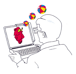
6. Eliminating the Need to Wear Polarizer
Glasses
The necessity for the observer to wear polarizer glasses can
be eliminated by letting the display screen wear the glasses instead. The use
of a magnifying lens becomes practical by encasing the two camera phones in
a small box with an opening on its cover. (In case of a laptop computer, make
a cover with an opening.) The box is made telescopic so that the depth of the
box is adjustable. As shown in Fig. 7, a polarizer sheet is placed in the opening
with its transmission axis at 135° from the horizontal
direction.
|
|
Fig. 7 Eliminating
the need to wear glasses.
|
|
The right half of the polarizer sheet is covered by a cellophane
sheet in order to change the direction of the transmission axis to 45°.
Even though a glass lens was used in Fig. 7, a plastic lens has the advantage
of lighter weight. If a plastic lens is used, it should not be placed between
any polarizer sheets because it may create birefringent fringe patterns due
to residual stress in the plastic lens. The plastic lens should be placed on
the outside surface of the box rather than on the inside surface.
It should be added that this approach is possible because both
a laptop computer and a camera phone normally have only one viewer at a time,
and the viewer instinctively holds his or her head in a position to match the
position of the display. But as the position of the eyes move away from the
opening, the range of the allowed lateral movement of the eyes decreases and
finally the tolerance becomes uncomfortably small.
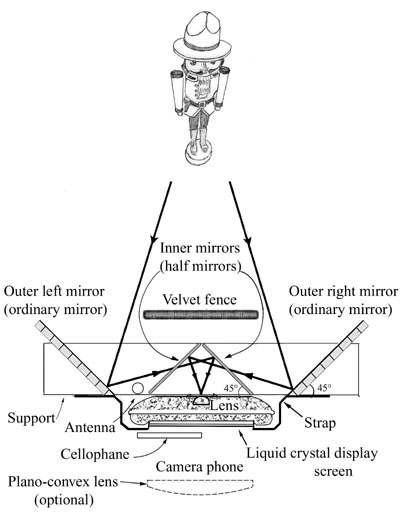
7. Using a single camera phone
It is possible to produce a 3D display using a single camera
phone. The display of a camera phone has to share two stereoscopic images, and
the left and right images have to be transposed. The details of the slip-on
stereoscopic mirrors are shown in Fig. 8 (from Ref. 4). The scene taken in by
the right outer 100 % reflecting ordinary mirror reaches the left side of the
stereoscopic image by way of the inner two 50 % reflecting half mirrors, and
similarly, that taken in by the left outer mirror reaches the right side of
the stereoscopic image. Thus, the transpose of the image is achieved.
|
|
Fig. 8 Diagram of
the slip-on stereoscopic mirrors.
|
|
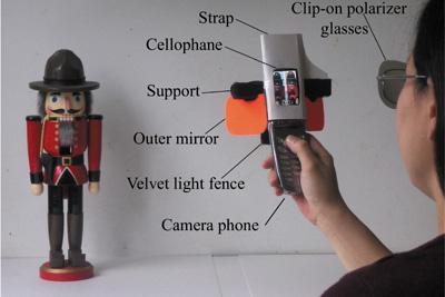
The slip-on stereoscopic mirrors have a wide strap to slip
the camera phone securely in place as shown in Fig. 9 (from Ref 4).
|
|
Fig. 9 Photograph
of slip-on stereoscopic mirrors.
|
|
One takes a pair of stereoscopic images by pressing the shutter key of the
camera phone. The stereoscopic pair is then sent to a dialed distant receiver
phone. On the receiver end, only the left half of the receiver phone's liquid
crystal is covered by the cellophane sheet so as to rotate the direction of
the polarization of the light from the left half of the liquid crystal display.
Thus, a stereoscopic pair of images with orthogonal polarization is made on
the receiver camera phone display. The observer at the receiver end can view
the 3D image by wearing a crossed polarizer glasses such as shown in Fig. 3
or clip-on polarizer glasses which can be flipped up for ordinary viewing. Figure
9 shows the operation of the slip-on stereoscopic mirrors.
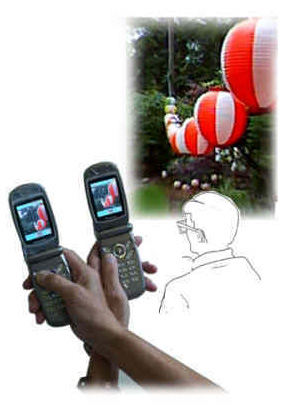
An interesting feature of this camera is that at the time the 3D picture is
taken, the composition of the 3D image can be readily examined on a preview
screen even before the shutter is activated if the cellophane sheet remains
on the left half of the display screen of the transmitter camera phone at all
times. It behaves like a real-time 3D display. The sender can examine the 3D
image. The 3D effect is more dramatic if the object is a close object like faces,
flowers, birds, pets or trains or gardens, but the 3D is not as effective with
far objects like scenery, mountains, or countryside. The sender can pre-examine
the photo before sending the picture.
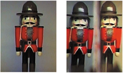
The quality of the transmitted 3D picture is compared with
that taken in an ordinary manner in Fig. 10 (from Ref 4). The slip-on stereoscopic
mirrors inflicted no noticeable degradation in picture quality.
|
|
Fig. 10 Comparison
of the 3D pictures. The picture on the left was taken in an ordinary
manner, and the right, taken with the slip-on stereoscopic mirrors.
|
|
8. Method Summary
A step by step method for fabricating the 3D image from a laptop
computer is summarized in Fig. 11, and that for fabricating the 3D image using
two camera phones, in Fig. 12.
|
|
|
|
(a)
|
(b)
|
Display what the right eye sees on the
left half of the screen, and display what the left eye sees on the
right half of the screen. Cover the right half of the screen with
the cellophane half-waveplate. To view, wear crossed polarized glasses
such as those shown in Fig. 3.
|
The 3D image that the observer sees.
|
|
Fig. 11
A summary of the procedure for converting
a 2D laptop screen into a 3D display.
|
|
|
|
|
|
(a)
|
(b)
|
Place two camera phones side by side
with a spacing of 6.5 cm. Take a set of pictures and dial the receiver
phones to send the pictures.
|
Transpose the received picture and cover the screen of
the left phone with the cellophane half-wave plate. To view, wear
crossed polarized glasses such as those shown in Fig. 3.
|
|
Fig. 12
A Summary of the procedure for converting
two camera phones into a 3D display.
|
|
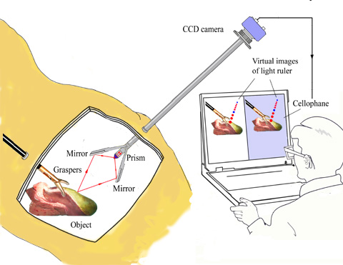
9. New Applications
Such a technique would have potential expansion into such fields as gaming,
consumer goods, scientific and medical applications. Most recently, the 3D technique
using a cellophane sheet was applied to a laparoscope
in order to expand the limited viewing capability of this minimum invasive surgical
device. A novel 3D laparoscope that can capture three-dimensional images during
surgery was reported11. The principle is solely based on the manipulation
of polarized light by a cellophane half waveplate rather than computer processing;
hence, there is no time delay (real-time operation) and lesions are viewed in
true color (important for diagnostics). 3D images are obtained with a single
laparoscope. A unique feature of this 3D laparoscope is that it includes a virtual
ruler to measure distances without physically touching affected areas. The structure
is simple, sturdy, lightweight, and its diameter is no bigger than a standard
10 mm diameter laparoscope.
|
|
|
Fig. 13
System of the 3D laparoscope.
|
|
10. Conclusion
In conclusion, a novel method to convert either a 2D laptop computer screen
or a camera phone screen into a 3D display was achieved by using plain ordinary
cellophane wrapping paper as a half-waveplate. The case of single camera phone
is reported in Ref (4). Applications to a 3D laparoscope are reported in Ref
(11).
11. Acknowledgment
The author expresses his gratitude to Mrs. Mary Jean Giliberto for converting
this paper into a Web-friendly format.
References
- Takanori Okoshi, Three-dimensional Imaging Techniques ( Academic
Press, New York, 1976).
- Keigo Iizuka, Elements of Photonics (Wiley & Sons, New York,
2002) p. 350.
- K. Iizuka, "Cellophane as a half-waveplate and its use for converting
a laptop computer screen into a three-dimensional display," Rev. Sci.
Instrum. Vol. 74, 3636-3639 (2003).
- Keigo Iizuka, "Three dimensional camera phone," Applied Optics
Vol. 43, 6285-6292 (2004)..
- Takehiro Izumi, ed., Fundamentals of 3D Vision (Ohm-sha, Tokyo,
1995) p. 64.
- J. Harrold, A. Jacobs, G. J. Woodgate, and D. Ezra, "Performance of
a Convertible, 2D and 3D Parallax Barrier Autostereoscopic Display" in
the Proceedings of the SID 20th International Display Research Conference
(Palm Beach, Florida, September 2000).
- J. Cutting and P. Vishton, "Perceiving layout and knowing distance:
the integration, relative potency and contextual use of different information
about depth" in Perception of Space and Motion, W. Epstein and
S. Rogers, eds. (Academic Press, New York,1995), pp. 69-117.
- E. Goldstein, Sensation and Perception, 3rd ed. (Wadsworth Publishing,
Belmont, California, 1989).
- H. Sedgwick, "The Geometry of Spatial Layout in Pictorial Representation"
in The Perception of Pictures, Vol.1, Alberti's Window: The Projective
Model of Pictorial Information, M. Hagen, ed. (Academic Press, London
1980), pp. 34-90.
- J. D. Pfautz, "Depth perception in computer graphics," Technical
Report number 546, University of Cambridge Computer Laboratory (ISSN 1476-2986,
2002).
- Keigo Iizuka,"3D laparoscope based on the manipulation of polarized
light by a cellophone half waveplate" accepted by Applied Optics.
Back