Keigo lizuka
Department of Electrical & Computer Engineering
35 St. George Street
University of Toronto
Toronto, Ontario, Canada M5S 1A4
The Divcam takes the ![]() decay
of the illuminating point source the yardstick for making a distance map. The
Divcam has two illuminating IR LEDs; one in front of the IR camera and the other
behind the camera as shown in Fig.1.
decay
of the illuminating point source the yardstick for making a distance map. The
Divcam has two illuminating IR LEDs; one in front of the IR camera and the other
behind the camera as shown in Fig.1.
Fig. 1 Divcam operating principle
The first picture I1 is taken only with the front LED lit, and the second picture I2 is taken only with the back LED lit with no other changes of arrangement. Each picture frame is taken into the frame grabber.
The pictures are identical except for their optical density. The ratio  is
taken for each pixel of the picture. The ratio R is large when the object is
close, but the ratio R monotonically decreases with an increase in distance
to the object, and finally approaches unity. The distance is calculated using
R.
is
taken for each pixel of the picture. The ratio R is large when the object is
close, but the ratio R monotonically decreases with an increase in distance
to the object, and finally approaches unity. The distance is calculated using
R.
The calculated result is displayed on a distance map such as the one shown
in Fig. 2. Figure 2(a) is a scene of a colorful object taken by a normal camera.
Figure 2(b) is the obtained distance map. The closer object is represented by
darker black. Figure 2(c) is the same depth map, but the depth is color coded
instead of black and white.
The reason for taking the ratio R is to remove the difference in reflectivity
according to the object color. By taking the ratio of I1 and I2,
the influence of color is cancelled out. The obtained distances of the red,
green, and blue of the Rubix cube are all in one plane in Fig.2 (b) or (c).
This proves that the color effect is successfully removed.
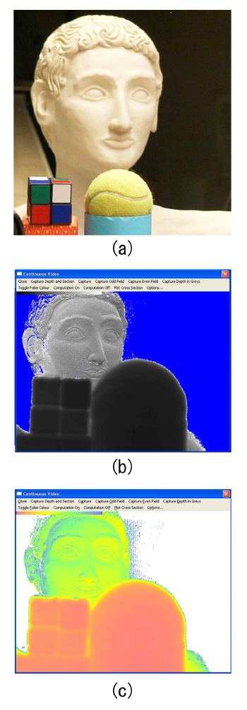
Fig. 2. Depth map of objects with various colors
Figure 3 demonstrates the ability to measure moving objects. A paper doll was pasted on a metronome so that the distance of the paper doll from the camera could be periodically changed. The color coded the depth map of the paper doll changed between red and blue as it swang.
Fig. 3. Swinging paper doll as an object.
Figure 4 shows the side view of an automobile that was derived from its front view depth map.
Fig. 4. An automobile used as the object.
(a) Depth map taken from the front.
(b) Side view of the automobile derived from (a).
Figure 5(a) is a photograph of a Kennedy coin taken with an ordinary camera.
Figure 5(b) is a relief of the coin taken by the Divcam. Since the Divcam uses
the ![]() yardstick of divergence
of a point source, the power of resolution increases as the distance to the
object is reduced.
yardstick of divergence
of a point source, the power of resolution increases as the distance to the
object is reduced.
Fig. 5 (a) Ordinary photograph of a Kennedy coin.
(b) Relief picture of the coin taken by the Divcam.