Design Project
PICTURES | Schematics
Design Project...
Here's a bunch of pictures of what I have been working on for the past year. Okay so I never finished! It happens... especially when you set out to build something fairly complicated.

In this picture you can clearly see the monster 7-pound weight and its guide-rails, along with the main structural elements. Those are 1x1x1/8 Aluminum HSS, bolted together using thin gauge galvanized steel plating and 1/8" x 1 1/2" machine screws. Along the left side (which is really the machine's right) you can see the circuits used to control the various activities of the device. Check out those wheels too! I got them at a remote control car store... they are Italian race tires imported from Italy. BWAHAHAHA.

A similar view but this time you can see the pulley system at the top... The wire is kind of slack here. It would usually be taught but ever since one of the gears in the winch system broke it has been like that.

Here's some badass circuit work personally etched by the other members of my team: Peter Lizon and Catherine Li. They were mixing some weird brown solutions and dipping in copper boards with intricate designs on them for hours. Don't ask me what these do... I only build the damn thing.

A view from the left of the machine. Now is your first look at the winch system at the rear and its great lookin' gearbox. More on that later. On the right of this picture you can see the prototype loading system going around the axis of the machine. The pulley is kind of out of alignment in this picture probably because we kept lifting the machine from the top and this jostled it around sometimes.

A closer look at the drive gears on the left rear of the machine. That's a good stepper motor geared down 10:1 or so... I don't recall the exact ratio. On an interesting note, I dropped that motor the day before our final evaluation and decidedly broke it. CHECK OUT THOSE SWEET TIRES.

A view from the rear of the machine.

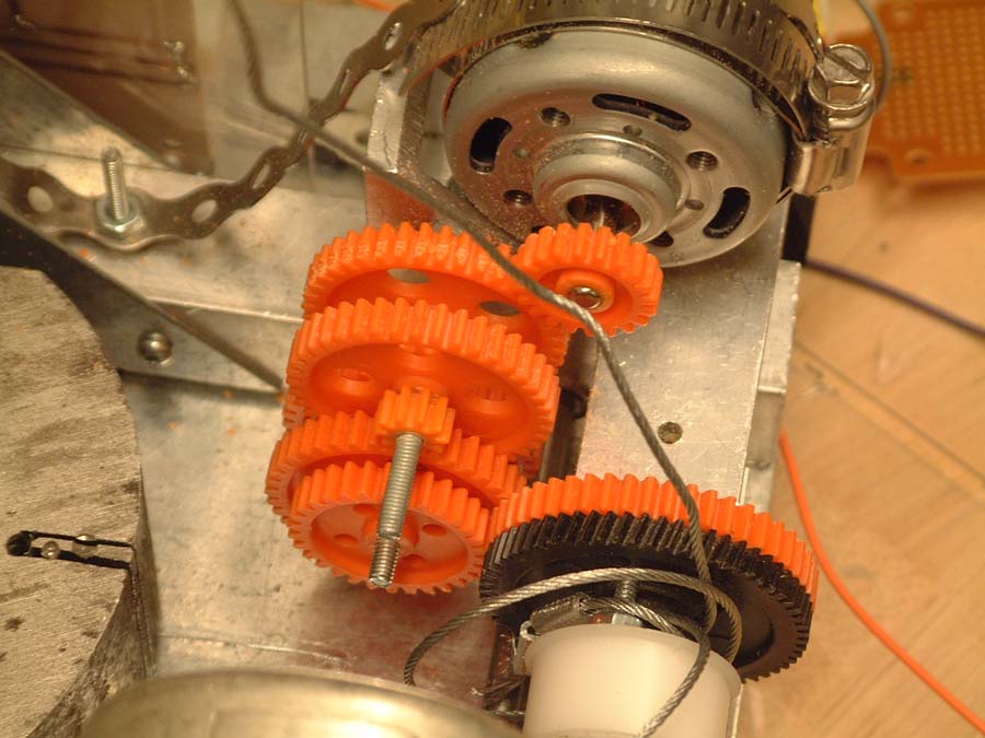
This is a closeup of the winch system... perhaps my favourite part of the machine. It's a pretty solid 213.3:1 gearbox that actually lifted and held that 7-pound weight for a while until one of the smaller gears just sheared off the glue connection. That motor near the top of the photo is a 24 W motor spinning at insane RPMs, but geared down you can't stop it with your fingers. Notice the notch along the first gear connection and all the particles of plastic strewn all over the place... this happened when once the motor slipped out of alignment and starting chopping away at the first gear. Plastic just kind of sprayed everywhere but I just tightened it down a bit more and it never happened again.

Overhead floorplan.

A plan from the rear of the machine.

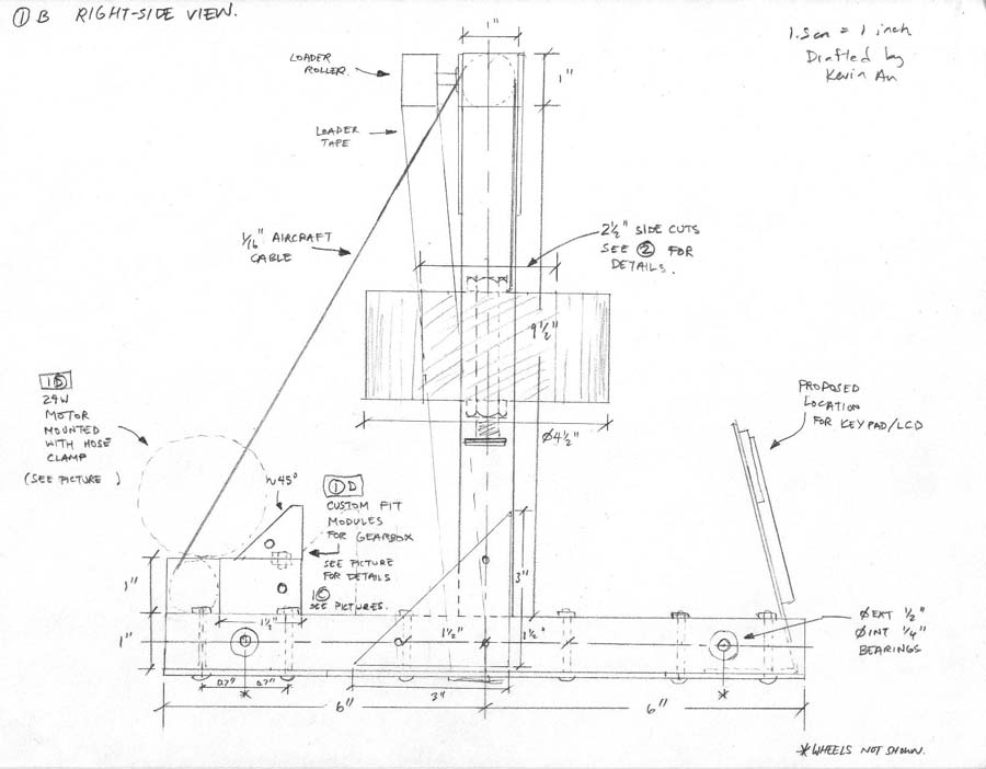
A plan from the right of the machine.

Hammer details.
Back to the main page


