|
ˇˇ |
|||||||||||||||||||||||||||||||||||||||||||||||||||||||||||||||||||||||||||||||||||||||||||||||||||||||||||||||
|
|
|||||||||||||||||||||||||||||||||||||||||||||||||||||||||||||||||||||||||||||||||||||||||||||||||||||||||||||||
|
ˇˇ(This is the site report when I worked in YPC-BASF
integrated petrol-chemical project in 2002.)
Keyword: pile engineering, YPC-BASF Project, bearing capacity, negative friction, precast-pile 1. BRIEF INTRODUCTION OF THE PROJECT YPC-BASF
integrated petrol-chemical (IPS) project is one of the biggest
petrol-chemical projects under construction in P.R.China. The
total investment is USD 2.9 billion. The ethylene unit is the largest
contract package of the IPS project, which is assigned to
Stone&Webster, a world leading engineering company. HQCEC is the
foundation & underground piping design subcontractor. The design began
in Sep, 2001 and ended in Sep, 2002. Due to the poor geotechnical
condition of the soil, cast-in-situ (CFA) concrete pile and precast(PC)
concrete pile were adopted for the equipment, piperack and buildingsˇŻ
foundations. Totally 3760 precast piles and 463 CFA piles were installed
by the end of the civil work. 2. CHOOSING
PILE TYPE AND DETERMINING BEARING CAPACITY 2.1
Application of different pile types
The new ethylene unit is located on the Yangzi
river flood plain alluvial area. Ground deposit material mainly consists
of pain filling soil on the top layer, silty sand and clay layer which is
30~40m in depth and highly compressive, mid sand layer and mud rock in the
bottom. Because some of the heavy and tall equipment, such as cracking
furnace, hot vessels transfer remarkably large compressive, tensile and
even lateral force to the foundation top. The natural ground canˇŻt
provide enough bearing capacity to sustain theses equipment. So the
cast-in-situ §¶800x60000mm pile was selected to meet these high bearing capacity
requirements. Design bearing capacity of §¶800x60000mm
cast-in-situ pile is shown in table 1.
Table 1 Bearing Capacity of §¶800x60000mm cast-in-situ pile
Besides
these very heavy equipment, there are still large amount of heat
exchangers, tanks, pumps and piperack foundations which are not very
heavily loaded in compression. But some of them are subjected to lateral
bundle force and pipe thrust force. ItˇŻs apparently not appropriate to
adopt CFA pile in these light equipment foundations. So 450x450mm2
squire precast pile was designed to meet the more diversified requirements
of light equipment foundations. The actual installed PC piles are 48m long
in average and the pile toe goes into the mid sand layer by 0.7m.
Design bearing capacity of 450x450 precast pile is shown in table
2.
Table 2 Bearing
Capacity of 450x450 precast
pile
2.2
How does failure load become design compressive bearing capacity Since
the 400x400 mm2 ,36m PC piles have been serving well in the old
YPC factory foundations for nearly 20 years. The same type of pile was
selected in the conceptual design. Totally 12 PC piles were tested for
their vertical compressive, tensile and lateral bearing capacity. And PDA
driving test, high strain (capwap) test and dynamic test were also done to
these piles. The failure load & design compressive bearing capacity of
the 400x400 mm2 ,36m PC piles is shown in Table 3
Table
3 Bearing Capacity of
400x400 mm2 precast
pile
According
to Pile Foundation Technology Code (PFTC) of China, the failure load
should divided by safety factor which is based on the probability theory
to become the design compressive bearing capacity. The lateral capacity is
defined as the lateral load that happened when the pile top has 6mm
displacement. 2.3
Comparison of different determining method
ItˇŻs regulated in the PFTC that class I & II (very important) pile
foundationsˇŻ compressive failure load can only be decided through load
test. But experimental formula method, which is based on the relationship
between soil property and the pile resistance, can be used to estimate the
class III pile foundations failure load. The experimental equation
presented by PFTC is
Qisk---pile
skin friction Qpk---pile toe resistanceu----pile
perimeter Li----
depth of each soil layer Ap---area
of pile section According
to 2.3.1, the failure compressive load of 400x400 mm2 ,36m PC
pile would be
We can see that the
experimental formula result is a little higher than the load test result
shown in table 3 and the pile toe resistance accounts for 45% of total
bearing capacity. Since the load test is the most reliable way to
determine the bearing capacity, we can draw a conclusion that the
experimental formula method is not conservative in some cases, itˇŻs
precision depends on the designerˇŻs experience to choose the Qisk &
Qpk factor. But this method can be used in conceptual estimation. Compared
with the capwap test results (shown in table 4) which reveal the actual
resistance distribution along the pile body, the calculated pile toe
resistance accounts for a much higher percentage than the actual
situation.
Table 4 CAPWAP TEST
RESULT OF 400x400 mm2 ,36m PC piles (kN)
2.4 Negative
skin friction
Because there exists about 20 meter highly compressive mucky
silt 7 meter under the ground and the whole ethylene unit was backfilled
with 3 meter plan clay only 1 year ago. The ground settlement is far away
from stable. ItˇŻs necessary to take the negative friction into
consideration. After consulting to URS, an geotechnical engineering
consultant, Stone&Webster decided to use longer piles instead of 36m
piles. The main concern is the negative friction. According to URS
estimate, the bearing capacity will be reduced by half and the 36m pile
will have little bearing capacity left. So 450x450 mm2 ,48m
long squire precast piles were finally chosen. The failure load obtained
through load test is shown in table 5. Table 5 LOAD
TEST RESULT OF 450x450 mm2 ,48m PC piles (kN)
The
experimental equation analyzed failure compressive load is: (according to
2.3.1)
The same problem is
revealed here that the experimental formula failure load is higher than
the load test result. But the pile toe resistance accounts for 26% of the
total resistance, which is much closer to the actual situation of the
resistance distribution.(see table 6)
Table 6 CAPWAP TEST
RESULT OF 450x450 mm2 ,48m PC piles (kN)
Comparison
of 450x450 mm2
,48m & 400x400 mm2 ,36m precast piles failure load are
shown in chart 1
3
CHOOSING HAMMER TYPE AND DRIVING CRITERIA
3.1
ItˇŻs important to choose an appropriate hammer for a good pile driving
performance. A heavy hammer would produce too much striking energy, which
will damage the concrete, especially result in concrete spalling or
cracking. PFTC recommends monitoring the striking compressive strain and
tensile train for piles requiring very strict crack control. But this
check is not mandatory in this project. A light hammer may result in the
difficulty in driving the piles down because insufficient energy canˇŻt
produce a substantial displacement between the pile and the soil. The
following table 7 is the code recommended hammer parameters.
Table
7 Hammer Parameters
Combining the code
recommendation, piling contractorˇŻs experience and the piling rig
manual, we finally decide to use 6t hammer. The total weight of a 450x450
mm2 ,48m PC pile is 25t ,a 6t hammer can transfer enough energy
on the pile to produce a plastic displacement. 3.2
The more complicated problem than choosing a hammer is the driving
criteria. To make the explanation more clearly, some terms need to be
clarified first. The refusal in the last 3
consecutive 10 strikes: the penetration measured in each 10 strikes just
before stopping driving. This value should be less than a preset number
(usually 4~8 cm for 6t hammer), which means the piles toe has reached the
hard supporting course and obtained enough resistance from it, so the
desired bearing capacity can be insured. The blows in the last 3
consecutive meters: although the refusal in the last 30 strikes can
disclose where the pile toe goes, the pile sometimes doesnˇŻt hit the
hard course suddenly, but goes through a rather long way in the sand
layers before it actually stops. The blows in a standard distance (eg.one
meter) can be used to measure this. If a pile undergoes more than 100
blows in each meter of the last 3 consecutive meters, that means it has
gone deep enough into the sand layer and enough resistance is obtained. Another way can also be used to judge
if the pile has reached the supporting course by comparing the pile toe
elevation with the supporting course contour map. The pile toe elevation
can be calculated by following equation:
Toe Elev = Top Elev ¨C pile length
(3.2.1) This method is also recommended by
PFTC. But as we know, the bearing course contour map was generated by
tieing the borehole point with curve lines. It canˇŻt be very accurate in
every pile location. So the principle in the PFTC to stop driving is: take
refusal as priority and elevations as reference for piles that penetrate
through hard soil layer. The driving criteria applied in this project are
shown in chart 2. We may notice that there is a category classified as Q70
in this chart. This type of piles was sorted out after consulting to URS,
because they didnˇŻt show very good resistance from the supporting course
but were qualified for light loading. Another
experience obtained from this project is the refusal criteria shouldnˇŻt
be made too stringent to the test piles, because the driving performance
of test piles is the most important basis to determine the driving
criteria. Excessively strict driving criteria can cause much trouble in
the construction. Many piles will have to be classified as
ˇ°unqualifiedˇ±, though they actually are good to take light or medium
load. Relatively loose driving criteria can also reflect the obtained
resistance and bearing capacity if combined with pile testing. 4.
CHOOSING A PILE LENGHTH
Usually the design
institute wouldnˇŻt point out the individual pile length. The drawing
will only show how deep the pile will be in the supporting course.
Therefore, itˇŻs the site work to decide the pile length. A
pile length can be calculated by changing equation 3.2.1 into
Pile length = Top Elev ¨CToe Elev
(4.1.1) Because of the same reason
mentioned above, the calculated pile length couldnˇŻt be very accurate.
But the site engineer should try to make the pile length more reasonable
than leaving piles sticking up in the air. If the over pile length
continue to happen in one area, the information should be transferred to
the site engineer ASAP for him to make a quick response. 5
PILE
QUALITY CONTROL
Besides
the curing date problem, the pouring sequence, jolt ramming and concrete
mixing are also the vital causes to the poor concrete quality. We actually
saw clay was mixed up with the rubbles in a broken pile top, which unclose
the poor concrete quality very clearly. 6 CONSTRUCTION CONTROL
Considering
many factors will affect the piling work, itˇŻs necessary for the site
engineer to set up a piling information database for a better construction
control. 6.1
Collecting the
data
According to the PFTC, each piling crew should record such
information as pile NO., blows in every meter, total blows, difference
between design elevation and actual elevation, the refusal in the last 3
consecutive 10 strikes and abnormal situation in uniform tables. This
information will help us make judgment on each pile. The workerˇŻs
records must be collected from the crew on a daily basis. 6.2
Setting
up a database
Having owned all the driving records, a site engineer
should classify the pile into different status, such as ˇ°OKˇ±,
ˇ°FAILEDˇ±, ˇ°TESTˇ± and ˇ°Q70ˇ±. The discipline of classification
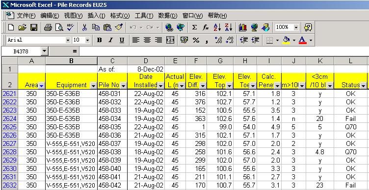
is shown in the chart 2. According to my experience, itˇŻs better to set
up an EXCEL database than sorting out original records all the time. A
typical pile records database is shown as chart 4
By
using the automatic filter tool, we can easily find out the desired result
and give quick response to field request. Another benefit for a computer
database is that different departments in a construction team can share
the information through Intranet. So more convenience would be provided to
the whole team. 7 PILE TEST7.1
There are two phases
of pile test. The first one is before the design commencing. Compressive
load test, tensile load test, lateral load test, PDA driving test, PDA
high strain test (one form of CAPWAP test) and dynamic test will be
carried out as we discussed in paragraph 2. The purpose of this phase is
to provide bearing capacity information for design. The second phase
happens during and after piling construction. The high strain tests are
usually employed to check the working pile integrity and bearing capacity
in this phase. Although these two phases are separated from time sequence,
they are related internally. For example, the PFTC requires that if the
compression test wasnˇŻt done in the first phase and the bearing capacity
was determined by experimental equation, then it must be done in the
second phase to check the actual bearing capacity. 7.2
In the second phase of
pile test, dynamic tests (high strain test and low strain test) are the
main methods to check the working pile integrity and capacity. One thing
that should be emphasized here is the principle in choosing the piles to
be tested. The PFTC recommend the selection of test piles shouldnˇŻt be
based on a random scope but should be based on a filtered scope. So the
selected test piles should be neither the ˇ°OKˇ± nor the ˇ°BROKENˇ±
ones, but those whose status canˇŻt be identified from the driving record
database. The relation between the actual tested capacity and the driving
performance is shown in the chart 5.
ˇˇ |
|||||||||||||||||||||||||||||||||||||||||||||||||||||||||||||||||||||||||||||||||||||||||||||||||||||||||||||||
| ˇˇ | |||||||||||||||||||||||||||||||||||||||||||||||||||||||||||||||||||||||||||||||||||||||||||||||||||||||||||||||