I saw this picture of the Mars Sojourner a long time ago, and have never
really forgotten it. Its 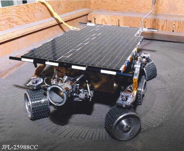 cool
how it can steer each of its corner wheels individually. This allows the robot
to turn about its own center without relying on skid steering. So of course I
wondered how I could possibly model this type of driving base out of Lego. I had
to come up with a different design, since I couldn't use individual motors to
steer each wheel.
cool
how it can steer each of its corner wheels individually. This allows the robot
to turn about its own center without relying on skid steering. So of course I
wondered how I could possibly model this type of driving base out of Lego. I had
to come up with a different design, since I couldn't use individual motors to
steer each wheel.
|
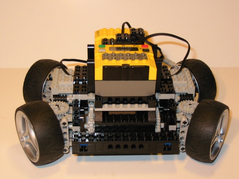
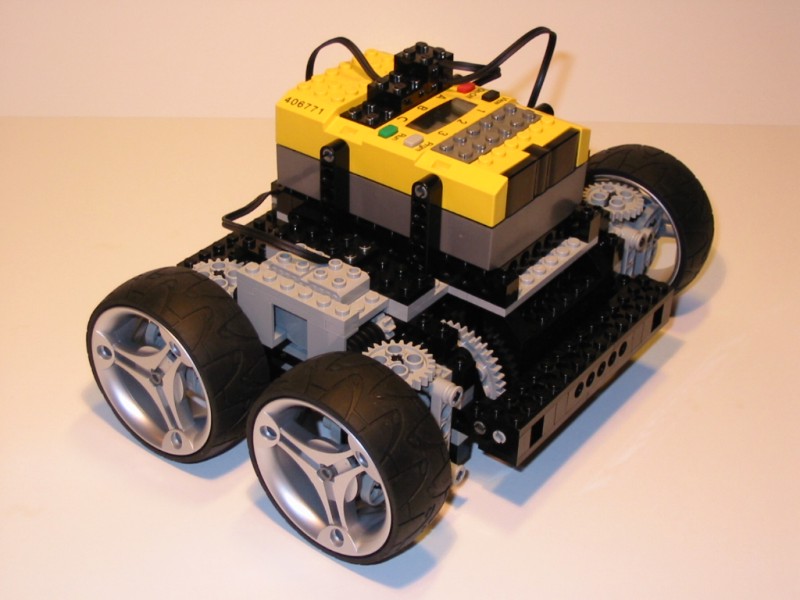
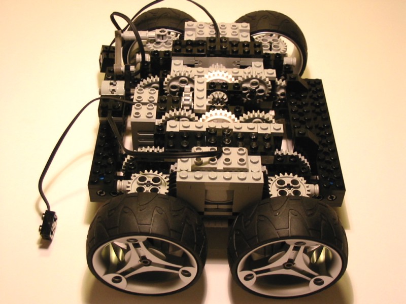
Front view. Unlike the Sojourner, this robot only has four wheels, but you can see how they all steer in a similar way. All wheels are powered as well. |
|
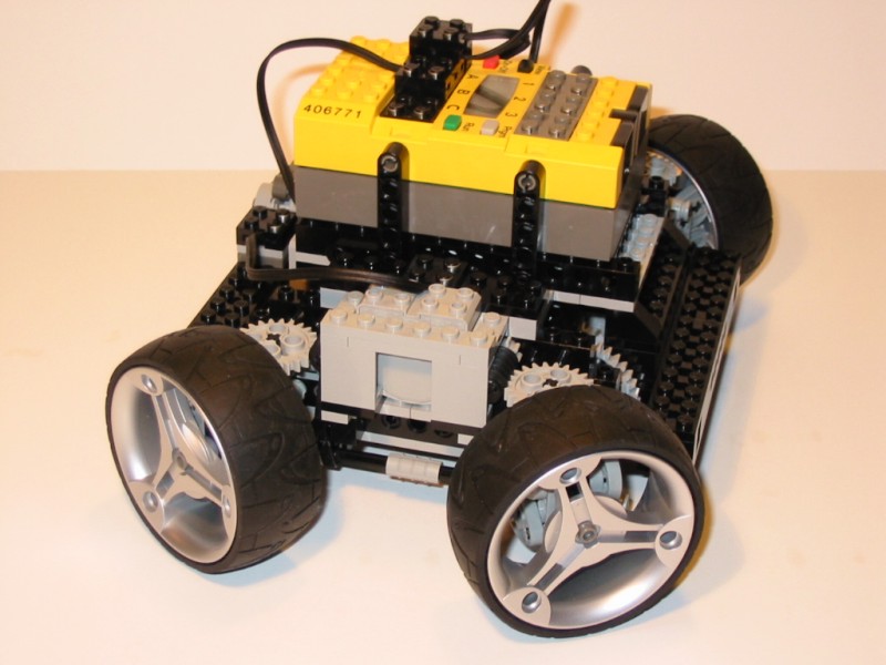
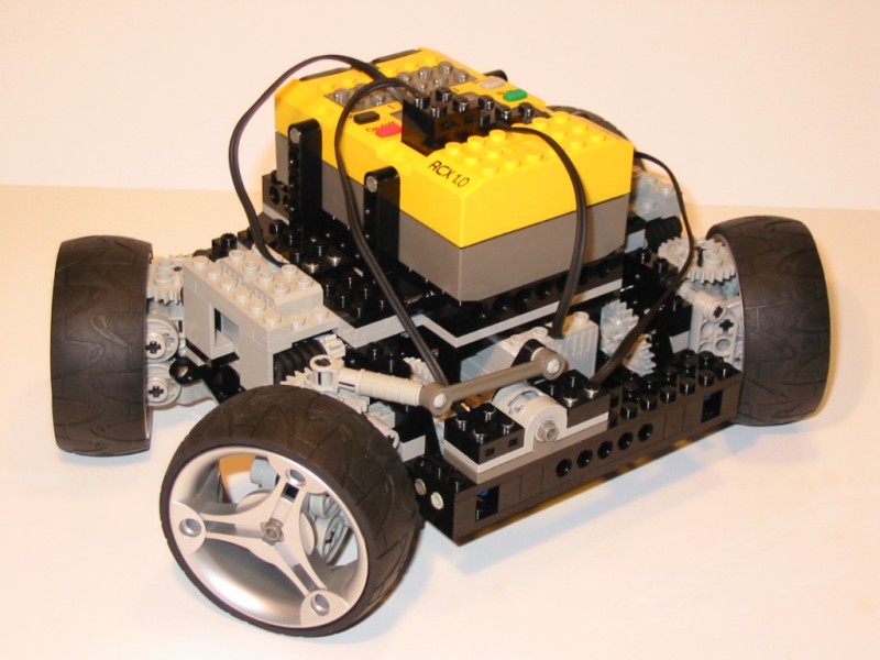
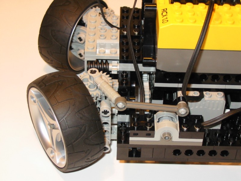
Side view. With the wheels in this configuration, the robot can turn about its own center. The wheels are all tangent to a common circle, so they do not skid. |
|
Side view with the wheels turned straight. |
|
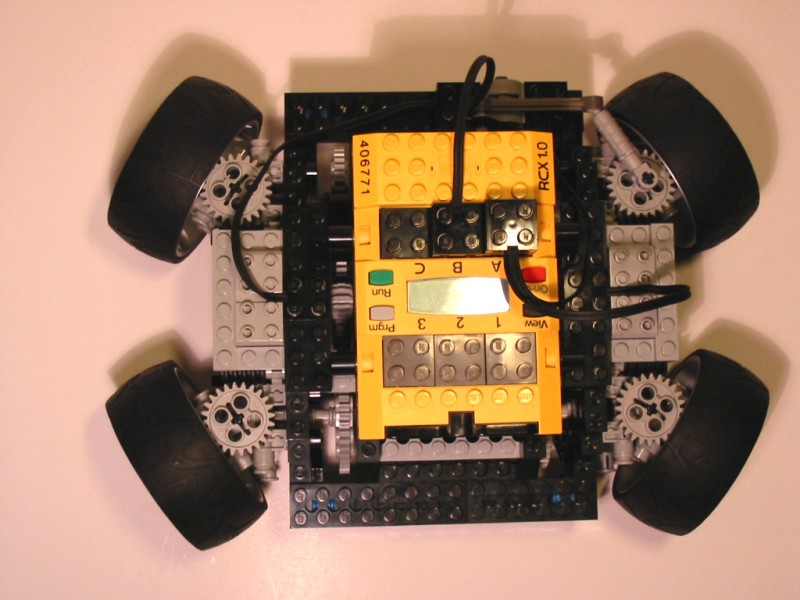
Top view. Notice how the diagonally opposite wheels are parallel. |
|
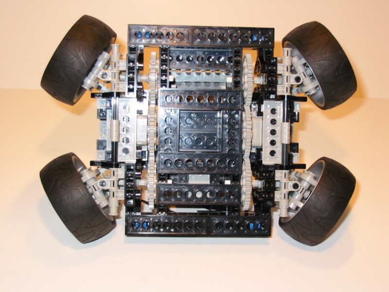
Bottom view. The wheels are connected to the 40t gears through universal joints. |
|
Rear view. Whats that crazy setup with the polarity switch? I'm glad you asked. |
|
Now, about the polarity switch... Both motors are powered from the same output. The left drive motor is connected to this switch. When the wheels are pointed straight, the motors turn in the same direction. |
|
When the wheels are steered completely, the polarity of the left drive motor is reversed, so it will turn in the opposite direction of the right motor. This configuration uses one output for steering, and one output for driving, so the third motor can be used for another function. |
|
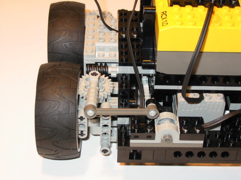
Side view with the RCX off. The two clutch gears power the worm gears at each wheel for the steering. The steering motor is in the middle at the back. |
|
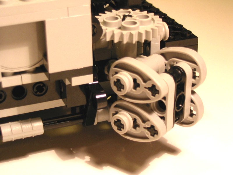
Close up of one of the steering arms (they are all the same). I borrowed the idea of this assembly from Fabio Sali. The cams provide a 1.5 unit spacing that is necessary to have the steering arm pivot about the center of the universal joint. |
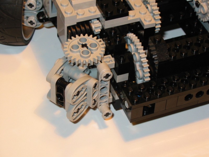
|
Another close up. Notice the non-standard mounting of the worm gear. It looks funny, but it works. The 8t gear is on the axle for spacing purposes only. |
This robot is really only a proof of concept (Notice it doesn't have any sensors). It is fun to watch how it drives around and steers, but it isn't quite strong enough for a practical application. Usually the more complex a mechanism gets, the less rigid and reliable it is. Universal joints aren't true 'constant velocity' joints, since the speed of the output shaft will fluctuate slightly when the joint is at an angle. The greater the angle, the greater the speed fluctuation. You could notice a very slight amount of shuddering due to this speed fluctuation when the robot was turning.