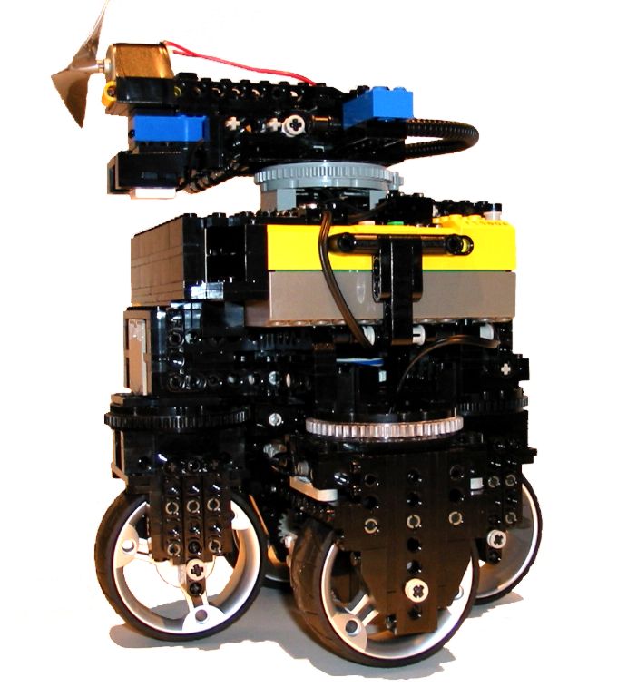
I have spent most of my holiday trying to improve my firefighting robot without making much progress. Don't get me wrong: this is not because its so good I can't make it better :) Its because I had to do things the hard way and build a synchro. Its very difficult to modify the driven/steering wheels. I have found there are two approaches to this design:
1) Mount the motor on the wheel assembly so it moves with the wheel as it steers. advantages to this approach are that the wheel doesn't have any turn induced by the gearing when it is steered. It is also usually a simpler assembly. The disadvantages are that the motor must ride with the wheel, so the driven/steering wheel assembly is bulky and the wires get tangled.
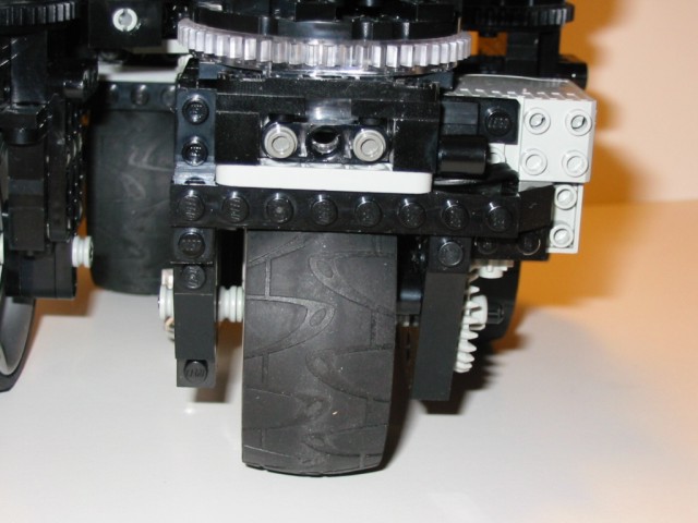
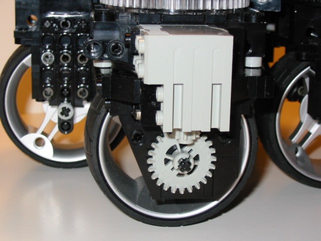
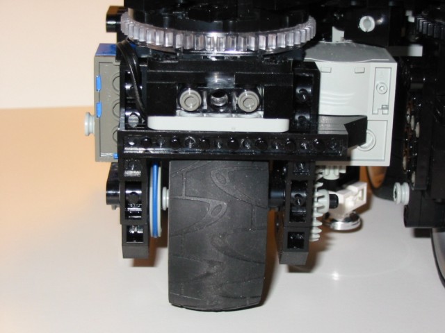
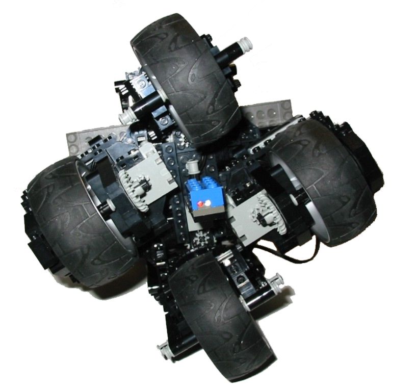
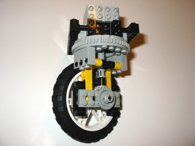
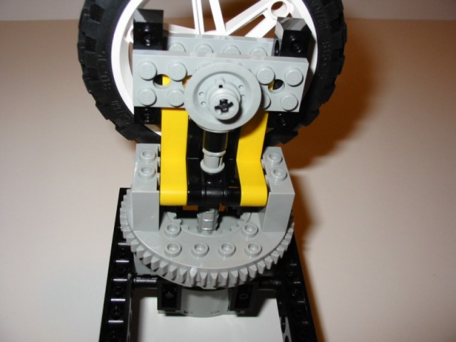
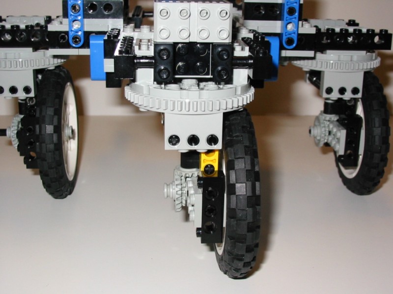
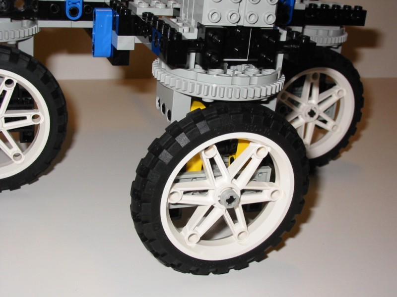
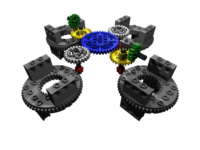
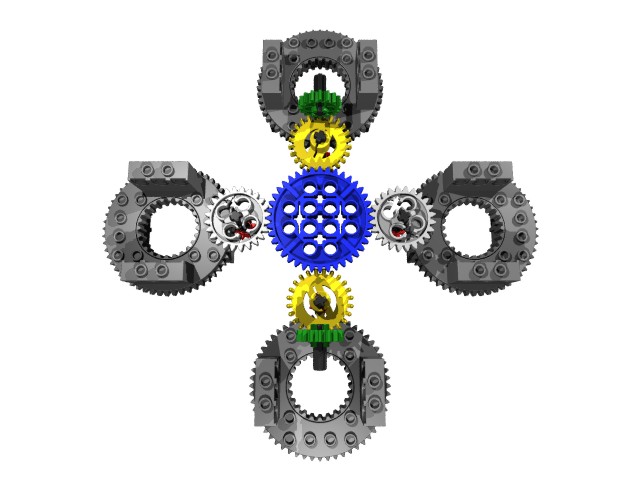
2) Use offset wheels and a clever combination of wheel diameters and gear ratios. In this way the gearing does force the wheel to turn as it is steered, but the idea is to tweak the parameters (wheel size, gear ratio, wheel offset) so the wheel will actually trace out an appropriate arc when steered so the base doesn't move. I have one design that is pretty close. I calculated the arc the wheel must travel to be 0.589 times the wheel diameter. The gear ratio is 0.6, (12:20 using the newish bevel gears). The huge advantage of this design is that the drive motor is fixed to the base and does not have to rotate. The disadvantage is the base is less stable because of the offset wheels. I believe this is how most real synchro bases are built, and I think the concept is worth pursuing further. If anyone has an alternative design, I would like to see it. There are several reasons I built this using large wheels: I want the robot to be fast and able to overcome obstacles.
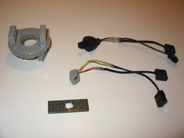
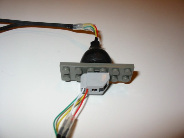
My original design of the driven/steering wheels was type 1. I got to thinking this would be the best way to go if only I could deal with the tangling wires. I made a Lego compatible slip ring using a phone cord detangler. John Barnes was extremely helpful and sent me a diagram on how to wire three sensors through the slip ring. The problem is, now that I made it, I don't want to use it. My soldering is pretty crappy, and the wires in the phone cord are so thin I'm afraid they will break or not be able to handle the current for the motors. So I try and make it better and quite possibly succeed in making it worse. Such is life.
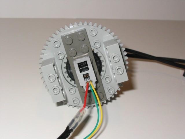
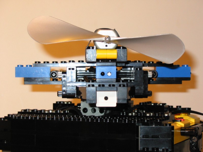
Another problem with a synchro robot is that the base itself never turns. Since my firefighting robot uses a wall following algorithm, it must be able to rotate the proximity sensors when it turns to follow a new wall. The same applies for the flame sensor. This creates the need for a rotating turret at the top of the robot which holds two proximity sensors (front and side), the flame sensor, and the fan or whatever else is used for extinguishing the flame. This means four wires must pass through a rotating assembly. The most that the slip ring assembly I made can handle is either one motor and one sensor or three sensors. So it looks as though the twisting wires problem prevails :( I have one final idea on how to solve this problem... I could try and multiplex four of the IR proximity sensors so the robot can detect walls from every side. This would prevent having to rotate the sensors. I currently have two of these sensors, so I can't try this idea yet, but I think it should work. Nearly all of the real synchro robots I have seen use a ring of sonar sensors for obstacle detection.
On top of trying to solve my mechanical problems, I have also been working on upgrading the robots program from NQC to BrickOS. Just installing BrickOS was quite a challenge. I eventually figured it out, and I would like to compile a set of instructions for other non experts like myself. The instructions I found on the web had many mistakes. I was also able to install the latest version of BricxCC which supports compiling and downloading of BrickOS programs. This makes it much nicer to work with. I no longer have to write my C programs in notepad, save them, and then go to the Unix shell to compile and download them.
Currently I have been able to translate most of the program into BrickOS. Both the master and slave RXC programs compile without errors (which was a very exciting moment for me). The basic features such as communication and drive commands work, but since BrickOS interprets sensor readings differently, there remains some work to be done in that area.
Why switch to BrickOS?? Well, I really like NQC, but I was getting frustrated with all of the limitations. It wasn't the amount of variables, but the size of them. I found it was quite easy to cause overflow when doing calculations with 16 bit integers. This became an issue when trying to convert the raw proximity sensor readings to an actual distance accurately. Another problem I had with NQC was the limited amount of memory left for program storage. I think out of the 32K available, the standard firmware takes 26K, so only 6K is left for programs. I nearly ran out of memory a couple times. This was because I used a lot of functions, and the standard firmware expands functions into inline code. I was able to get around this by using subroutines (which are smaller because the code is reused), but it was awkward. The BrickOS kernel is about 10K (I think), so you get 22K for your program. Finally, my greatest annoyance with the standard firmware is that it is based on an interpreter. This means a NQC program is translated into bytecode, and then must be interpreted into machine code as the program runs. I never understood the reason for this. BrickOS programs are compiled straight into machine code, so they run about 100 times faster. This wouldn't make much of a difference in most applications, but when the robot has to perform calculations and dynamically adjust to sensor readings, the extra speed can make a big difference. This is what makes Steve Hassenplug's Legway possible. The nifty sensors from Hitechnic also make the impossible possible.