A while ago, I was looking on the web for information on gears. At the how stuff works site, I was reading about worm gears, and it said that a Torsen differential was an interesting application of worm gears. This caught my attention, so I began looking for more information. Eventually, I thought it would be cool to build one out of Lego :)
I thought this picture explained it best. When looking at the other diagrams I found, I was confused as to which gear was the worm, and which gear was the worm wheel. The worm has multiple starts, so it looks more like a crossed helical gear. Knowing which gear is which is critical to understanding the Torsen differential, since it exploits the fact that worm gears cannot be back driven. It took me quite a while to understand how this differential works. Here is the way I see it: the only way this gear train can be driven is if both shafts turn at equal and opposite rates. This is exactly the motion needed for a differential, because as a car goes around a turn, the outside wheel turns x mph faster, and the inside wheel turns x mph slower. Although both wheels are turning forwards, the inside wheel is turning backwards relative to the outside wheel. If one shaft slips, or tries to turn at a different rate, the worm wheels lock up on the worm gear, and traction is preserved
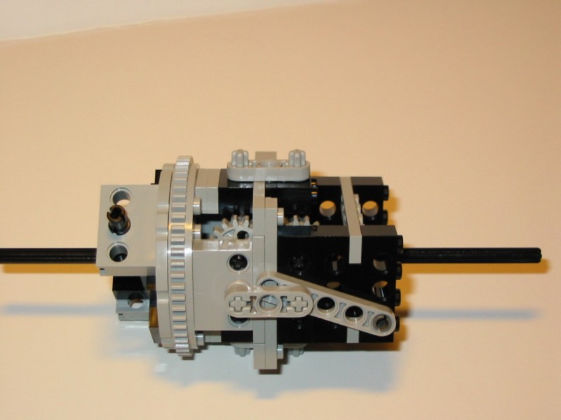
My Lego version..
|
|
Side view. Its pretty big, I know... One good thing about using the turntable is that the diff could be held quite rigidly on the stationary end. |
|
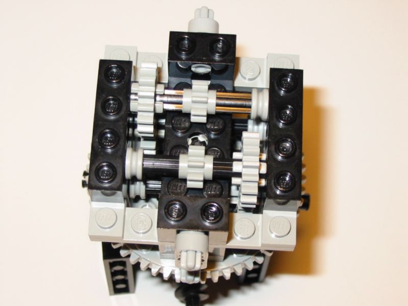
Picture with the top plate off. There is almost zero clearance between the 8 tooth gears and the plate underneath... not good. I couldn't think of another way to support the shafts in the center. |
|
|
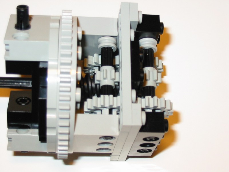
This picture shows the inner workings: The 8 tooth gears mesh with the worm gears, while the two shafts are coupled with the 16 tooth gears. this produces the necessary counter-rotation. |
Final thoughts... This version of the Torsen differential is pretty close to the configuration of the real thing. Unfortunately, it is too big and impractical to be used in most models.
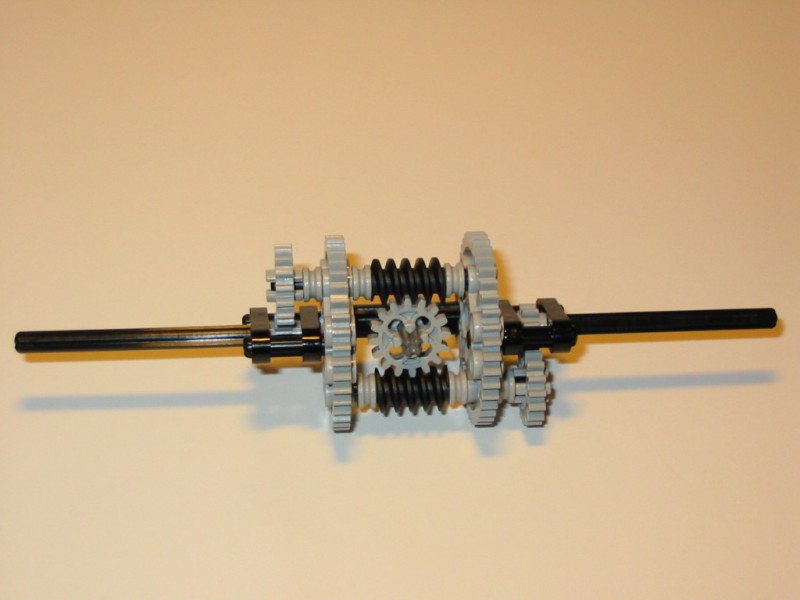
Now, a more Lego friendly version. I got to thinking about the Torsen differential, and how it could be simplified. I realized that I could change the configuration of the worm gears, and significantly reduce the size and number of parts required.
|
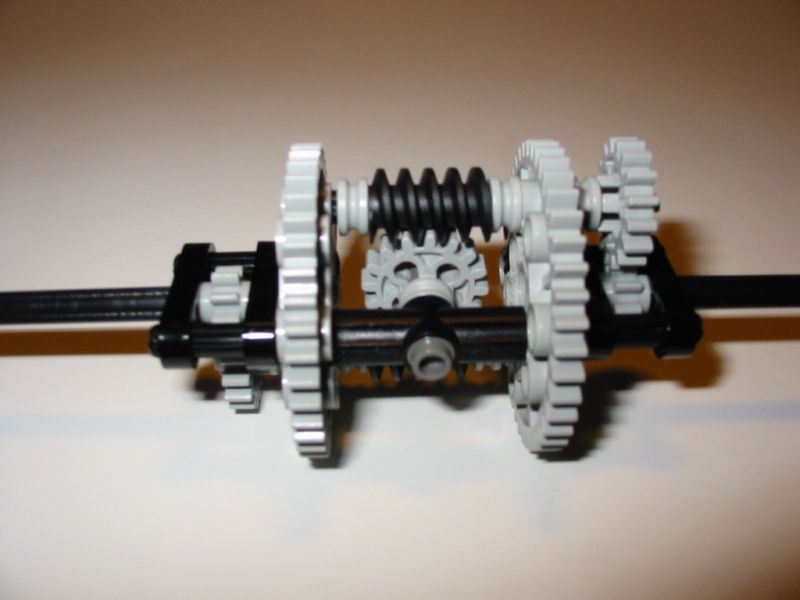
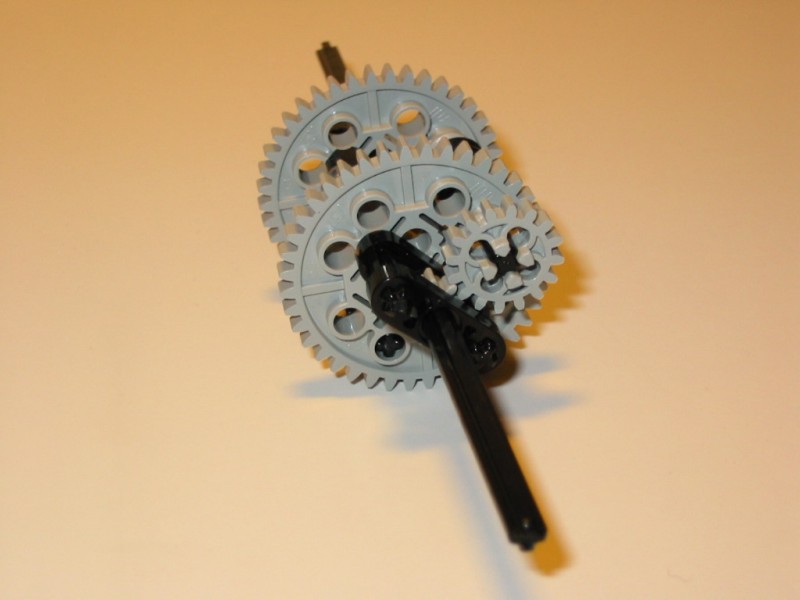
A blurry close up, but I kind of liked the lighting... |
|
Side view. The main difference is that instead of having multiple counter rotating gears meshed with the outside of the worm gears, I used a single gear in between two worm gears. The end result is the same. One thing that needs to be improved is that the shaft holding the 16 tooth gear is only supported on one end. I couldn't figure out a nice way to support the other end, because the spacing is offset. I am open to suggestions. |
|
End view. I borrowed the gearing for the ends from Mike Fusion's page. |
Final thoughts... I like this version of the Torsen diff much more. It is smaller, simpler, and more realistic. It is only slightly larger than the custom built Technic differential seen here. With some modifications to the Lego parts, this diff could be way smaller, but I'm not going to do this. When was the last time a Lego car really needed a Torsen diff anyway? I just like building mechanisms to see if it can be done. And, I have a much better understanding if how a Torsen differential works now. Class dismissed.