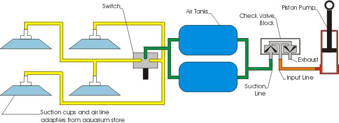
The diagram above illustrates how the pneumatic components are connected to produce suction for the window walker. The key components are from old Lego pneumatic sets that are no longer produced. First, an old style piston serves as a piston pump. It is connected to the input of the old style valve block. Contained within this valve block are two check valves. These check valves allow the air to flow in one direction and not the other. I have tried to show schematically how these would work. According to my diagram, the air can only flow in the direction the black 'V's are pointing. The actual check valves inside the Lego piece are flexible diaphragms. When the piston is pushed down, the air is blocked by the check valve on the left, and is able to pass through the check valve on the right, leading to the exhaust. When the piston is pulled up, the right check valve closes, and air is sucked though the left check valve. This is how suction is produced. The suction line is connected to the air tanks, so as the piston is pumped, the air is drawn out of the air tanks, and a vacuum is created. The tanks are connected to the input of the two way switch, and the outputs are connected to diagonally opposite suction cups. As the window walker is climbing, its diagonally opposite feet move together, and the switch is toggled back and forth between the two pairs of suction cups. Flipping the switch will release one set of feet while simultaneously engaging the other set of feet. Every time all four of the feet are at the same level, the suction switches from one pair to the other. As you could imagine, timing is everything. Let me tell you, the window walker fell many times before I got it right!