ACADEMIC PROJECTS
- Background:
pyMDO is a joint venture of University of Toronto MDO lab and the Aerospace Computing Lab (ACL) of Stanford University. The motivation of the project is to provide a platform for engineers to assess preliminary design concepts with little minimal turn-around time.
- Description:
My role in this project was to study the use of the constraint handling method, Kressielmeier-Steinhauser Function, regarding its effect on the overall optimization process and results.
- Method:
The Kressielmeier-Steinhauser Function was compared with other methods and found to be efficient in reducing process time. However, it was found to return significantly less accurate results than "Status Quo" (no constraint handling is used)
- Results:
Derived a adaptive formulation that eliminate the inaccuracy while increase the overall performance of the process.
Revised Stress Constraint Handling Formulation on CSM Module
|
|
- Background:
In classic flight dynamics, rigid body assumptions are made in the derivation of the equations of motion and the determination of the vibration mode.
However, as recent aircraft design concept feature high speed, light weight and low structural stiffness, more significant control-structure interactions are introduced to the flight dynamics calculation.
Therefore, flexible vibration modes of the structure become more prominent in recent aircraft concepts such as supersonic cruise aircraft (SCRA) and high-speed civil transport (HSCT). In these concepts the control-structural coupling effects strongly affect the control and ride qualities.
If these are not properly handled, it may lead to serious fatigue problem and thus degrading life cycle of the aircraft.
In this respect, approaches are needed to handle the control-structural coupling effects.
- Description:
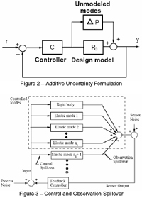
In this project, a robust controller, namely the linear quadratic regulator (LQR) control design will be studied and applied to the pitch control of an SCRA concept.
With the application of the LQR approach, controller can handle the rigid body modes (classic flight dynamics) and the prominent flexible modes (coupling effects) while having a margin accommodating the non-prominent flexible mode as uncertainties.
- Analysis:
By performing order reduction, the full order model (40th) was reduced to an 8th order model that account for the rigid modes and the two prominent flexible modes. High frequency modes are truncated by ranking the opterator norm Hinf.
The remaining unmodeled flexible modes were treated in parallel to the primary system as additive uncertainty for the controller.
- Results:
The controller designed offer robust stability in the presence of unmodeled flexible modes.
Furthermore, uncertainties in the unmodeled dynamic are tolerated without instability as long as the magnitude plot lies below the uncertainty envelope.
However, the results indicate that it is difficult to improve aeroelastic mode damping using the elevator as the only input.
|
|
- Background:
A FEM program was developed as the Computational Structural Mechanics Solver in the low fidelity multidisciplinary design optimization (MDO) framework for a wing design exercise. This exercise provided insight of the MDO framework operation and interface specifications.
- Description:
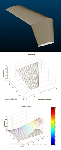
The FEM designed for plate bending problem features Reissner-Mindlin Plate Theory and is intended for filled-core wing analysis. Typical application of this type of structure includes home built general aviation aircrafts, model planes and unmanned air vehicle (UAV), which are common flight vehicles with filled core wing/empennage structure.
- Analysis:
Used a unit plate model to ensure the convergence of the FEM code.
The FEM analysis starts with adopting the mesh and loads from the output of a panel code aerodynamics solver.
The wing is then modeled as a continuous plate with the mean thickness of the original structure.
The mesh is denser at the leading edge where the load would be higher compare to the trailing edge.
In the FEM analysis, the wing root is assumed to be a clamped side with all other sides free to displace.
|
|

|
High Lift Devices and Control Surfaces Specialist (Structure)
Carleton University, Ottawa, Ontario |
Sep 2002-Apr 2003 |
- Details:
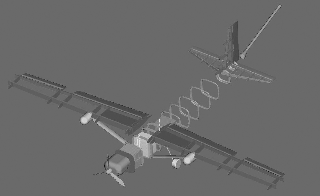
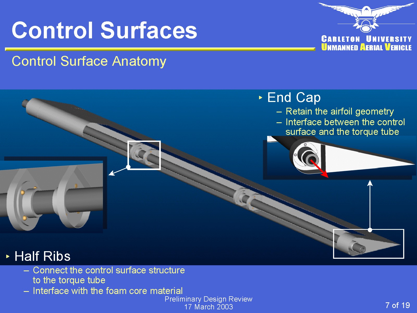
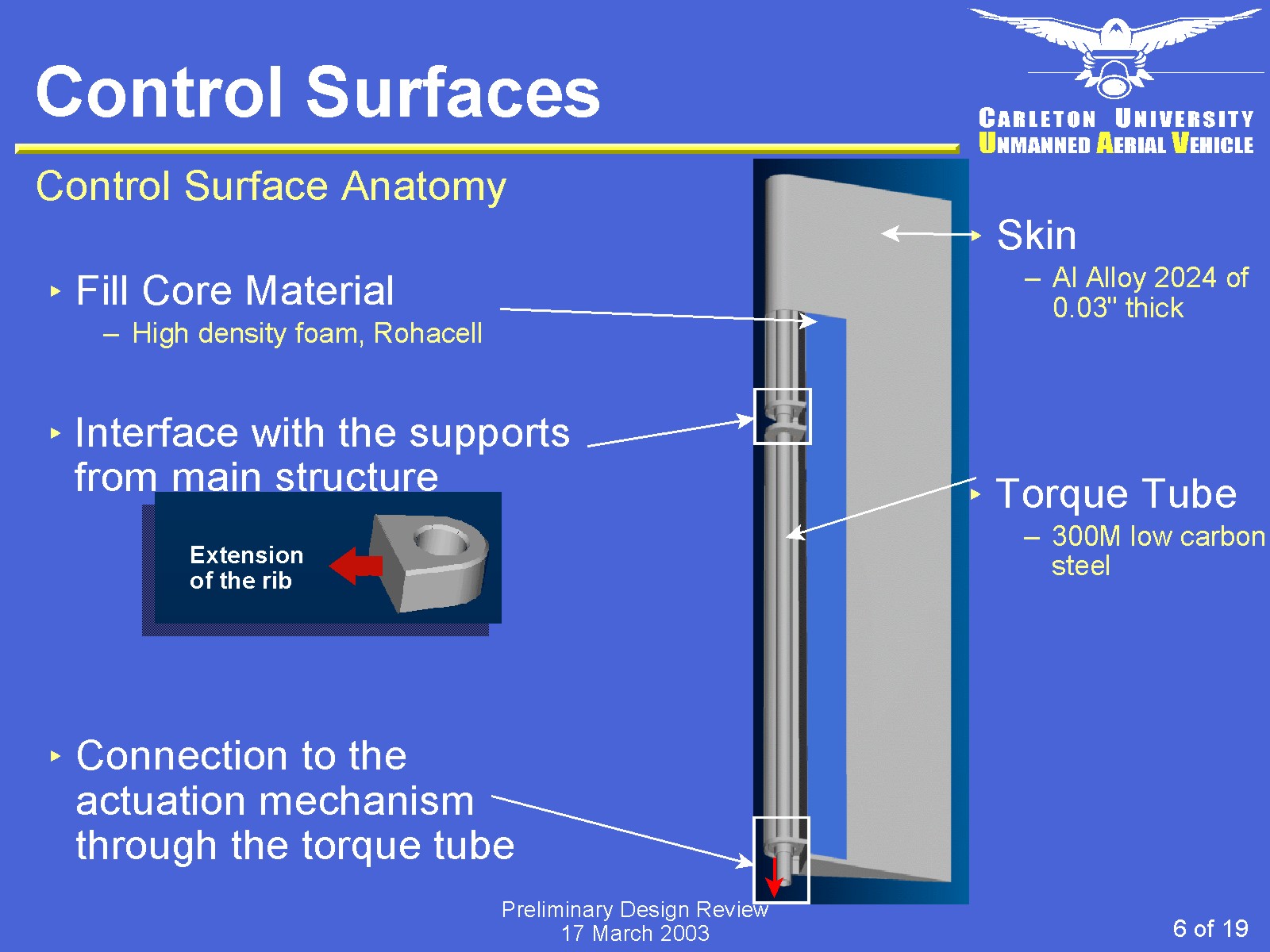
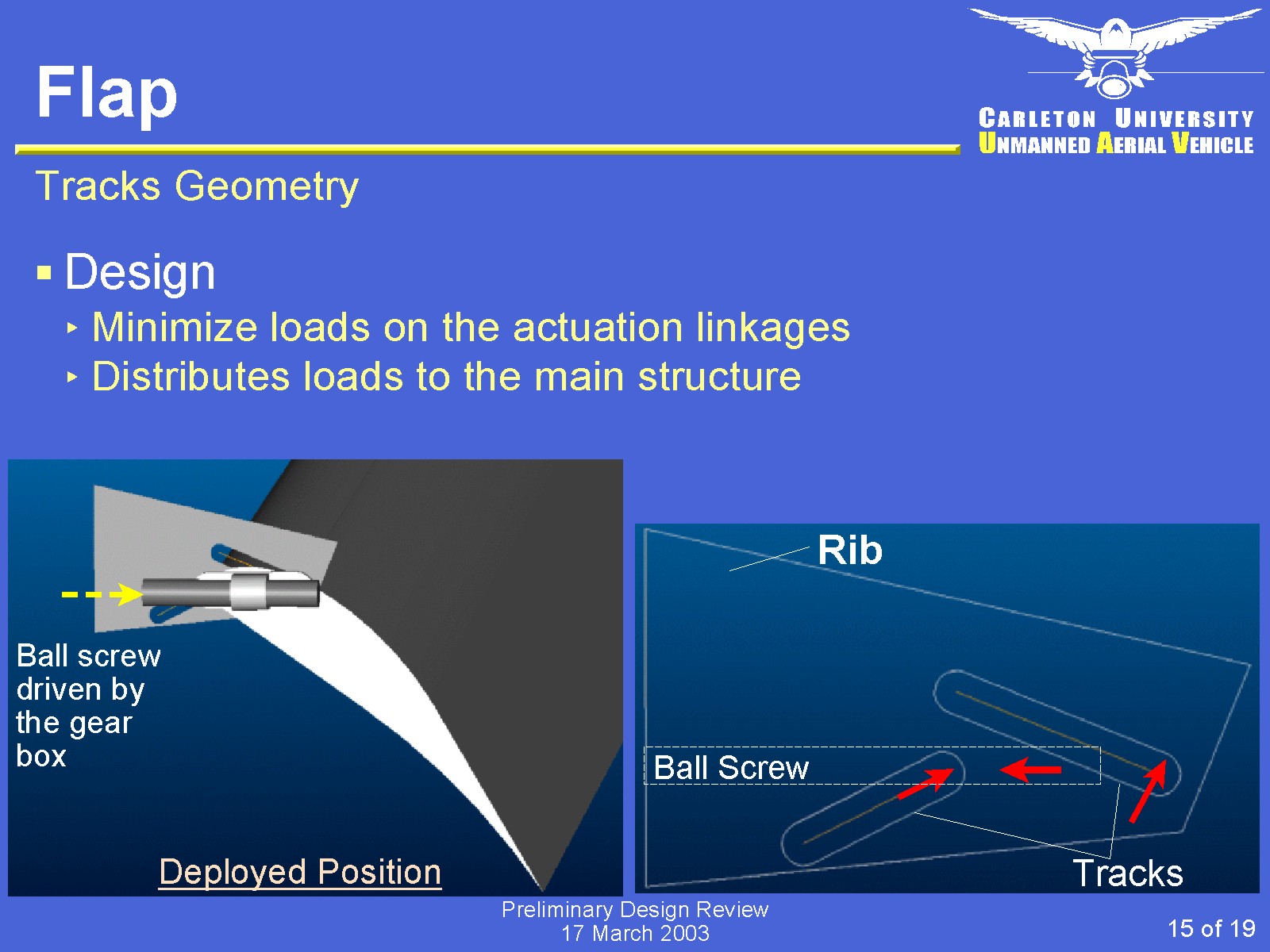
The structure scheme of the control surfaces and the flaps is a Hybrid Structure of fill core airfoil and half ribs supporting the leading edge.
This design will provide sufficient structure strength and reliable connection to the actuation linkage yet light in weight.
Also, this design holds the flexibility of upgrading the load bearing ability simply by increasing the thickness of the ribs and the wall without major changes to the overall structure scheme.
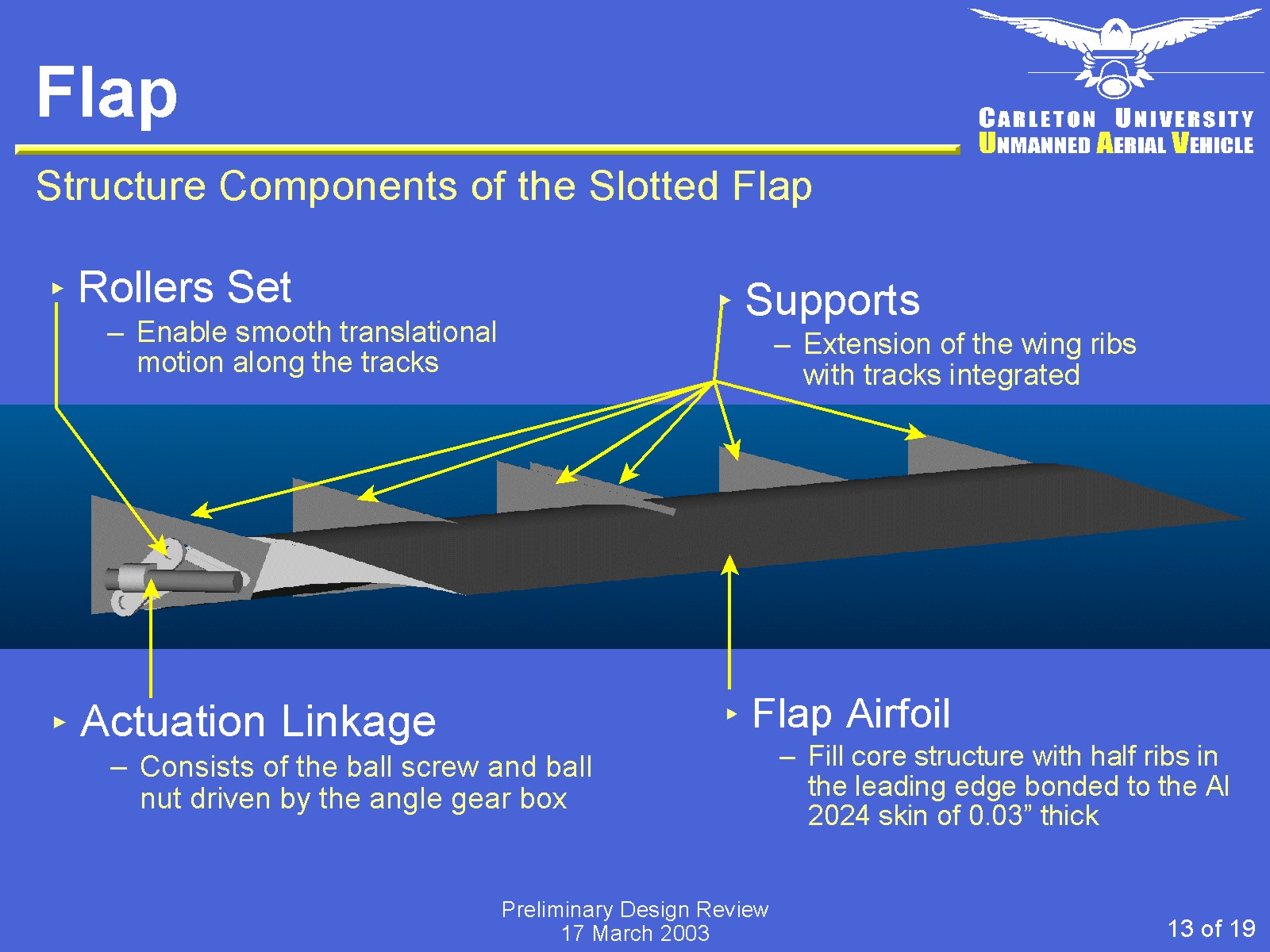
The Tracks and Rollers configurations used for the flap deployment satisfied the Aerodynamics requirements and ensure that loads on the flap is mainly transferred to the tracks and the actuation linkages are relaxed from extreme loading that may cause jamming. The structure integrity of the flap is proven by the bending and shear analysis of the flap airfoil to have sufficient safety margin from failure conditions.
- Results:
- Completed preliminary structure design for surveillance mission
- Liaised with aerodynamicists to arrive at the efficient flap geometry and deployment trajectory design
- Designed structure that satisfies low altitude flying requirement and corresponding sections in the federal aviation regulation, FAR 25
|
Conceptual Design
|
Preliminary Design
Internal Structure
|
Control Surface Structure
Structural Material
|
Flap Structure
Deployment Mechanism
|
- Description:
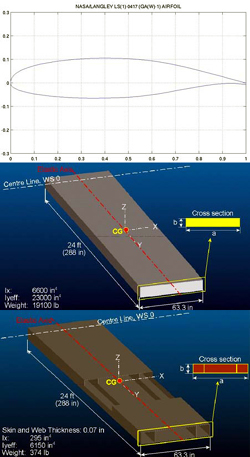
The static aeroelasticity analysis of the UAV GeoSurv has been conducted as the practical project for the introductory course on aeroelasticity.
Static aeroelasticity problems deal with divergence, control effectiveness and control reversal.
- Geometry:
High Lift Airfoil - LS1011
- Structure:
Both a solid cross section and a hollow section have been considered
- Results:
The hollow rectangular beam with internal spars is a good representation of the actual wing spars configuration of the GeoSurv.
The value calculated for the divergence speed from the second model suggest that divergence would occur at a much lower speed than the predetermined value of the actual UAV.
The divergence speed calculated from the second model is more conservative than the value from the actual GeoSurv UAV, providing a margin of safety.
|
|
- Requirements:
The designed main landing gear system includes the number of struts and wheels per strut required; tire selection with a 25% growth factor; the design of a retraction/extension mechanism with external downlock and uplocks. A electrical system has to be integrated so as to confirm the downlock and uplock configurations, monitor tire pressure and brake temperature, as well as prevent anti-skid and shimmy conditions. When designing the main landing gear system, our team take into account for the constrains of the physical parameters, aviation regulations, and safety margin.
- Design: Conceptually designed a main landing gear (MLG) system suitable for landing conditions range from grass field to rigid pavement
- Configuration: Tricycle arrangement with hydraulic retraction/extension system
- Maximum Load: 40,480 lbs (92% of MTOW, 44,000 lbs)
- Tire Sizing/Selection: Type VII Michellin tire of 45 in. diameter
- Shock Absorbers: Oleopneumatic shock strut with fixed orifice
- Retraction/Extension Mechanism: Forward retracting four bars mechanism
- Monitoring System: Uplock/downlock Confirmation, Tire Pressure, Anti-skid system, Brake Temperature & Shimmy
- Demostration: Constructed a scaled physical working model of the retraction/extension mechanism with external downlocks and uplocks for proof of concept.
|
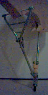
Mechanism Demo Model
|
- Cruise Speed: 155 kts at 75% power
- Cruise Altitute: 8,000 ft
- Payload: 950 lbs
- Stall speed: 55 kts (clean); 48 kts (flaps)
- Take-off field length: 1700 ft (SL)
- Range: 600 nm
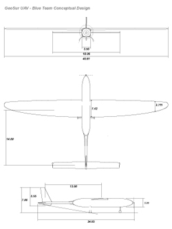
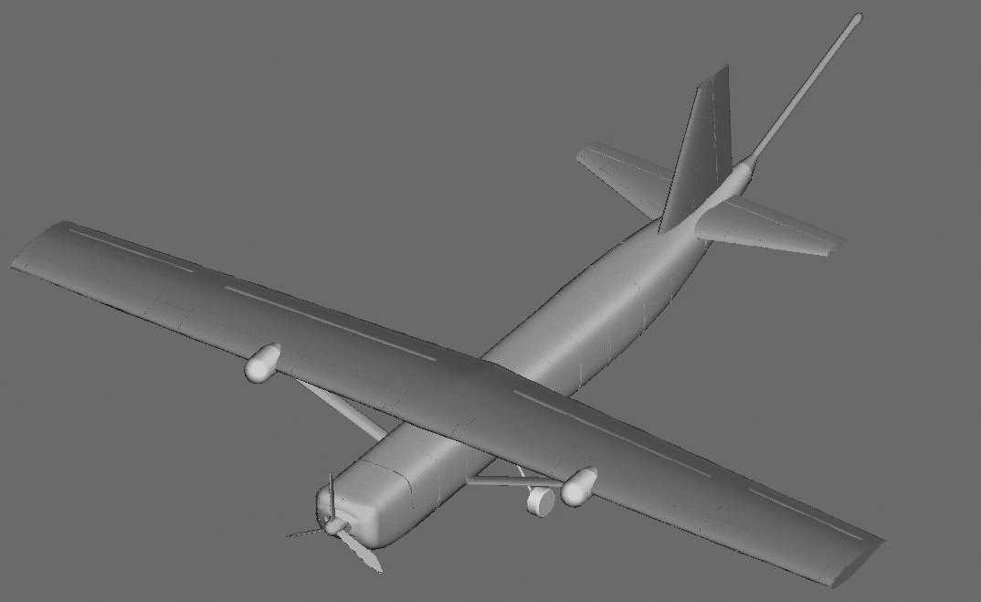
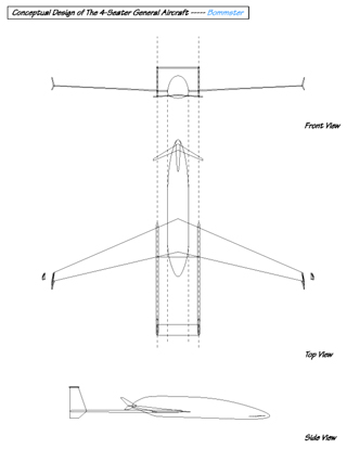
- Description of Design Concept:
As many of the new general aviation and homebuilt aircraft like Velocity has proven that the canard configuration is a desirable arrangement for safety in manoeuvring. However, planes like the Velocity with the use of the control canard suffer in the difficulty in manoeuver and risk in pitchup.
Therefore, the Three-Surface arrangement is chosen to allow the use of a small size lifting canard to ensure adequate control power and to reduce the induced drag on the wing while eliminating the difficulty of incorporating wing flaps as seen on a canard only configuration. Also, the three-surface arrangement offers reduction of trim drag.
The advantages offered by the three-surface arrangement would be sufficient to overweight the drawback of additional weight, complexity and interference drag associated with extra surfaces.
- The detailed descriptions of the aircraft�s features are outlined below.
|
|
- Requirements:
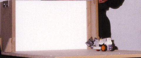
A Mining Vehicle capable of advancing to a 17.75"x11.75"x4" block of styrofoam, and then to remove material from the wall in order to allow the vehicle to make continuous progress through the solid.
- Constraints:
- Vehicle size not to exceed a 6"x6"x9" size envelope.
- Vehicle shall be powered by a mzimum of two "AA" batteries and a maximum of two 1.5 VDC motors.
- Design Features:
- Use of planetary gears to maximize the torsion output from the motor for drilling action.
- As drilling requires more power than the forward motion, the circuit is arranged in parallel for efficient power supply.
- Weights are added on the vehicle to offset possible tipping motion when drilling proceed.
- Ranked the 3rd out of 25 teams
- Description:
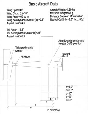
The objective of this experiment is to explore the requirements for stable longitudinal flight of aircraft where both Static and Dynamic Stability are studied.
- Method:
In this experiment, a radio-controlled aircraft is placed in a wind tunnel. While the aircraft is "pinned" on a steel tube, the movement is restrain to up and down only.
The propeller drive and radio controls were checked to ensure they would function properly first and the weight is attached in the front part of the aircraft. After turning on the tunnel, the aircraft propeller speed was increased. Next, the elevator was manipulated to make the airplane take off. Finally, the measurements of the angle of attack and the elevator angle were taken at different speed sets for both flaps on and flaps off.
By measuring time and the air speed in the tunnel using a sensitive manometer connected to static pressure taps on the tunnel contraction, aerodynamic derivatives are determined for respective analysis and settings
- Result:
From this experiment, the static stability of aircraft is studied using different control surfaces setting and airspeed. On the other hand, the dynamic stability is studied through the aircraft's responses after small disturbances are instilled.
|
|
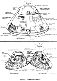
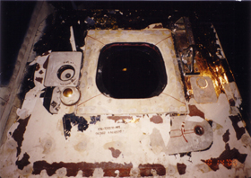
- Location:National Museum of Science and Technology, Ottawa, Canada
- Source: Apollo 7 mission - First manned spaceflight test of Apollo moon-flight system launched on October 11, 1968.
- Material: Aluminum alloy 7075-T6
- Structure: 7075-T6 sheet-aluminum honeycomb bonded as sandwich covered by the heat shield
- Attributes: Provide a housing for the crew, contain the required leak-proof cabin environment and meteoroid protection in the reentry vehicle.
- For details of the structure and material properties, please refer to the document here, [PDF].
|
|
|