This robot was built for a local Lego robotics competition: ProjectX. The task was to build a robot that could sort 8 randomly placed blocks into an X pattern within a 4 cell by four cell grid. This means that the robot had to simultaneously figure out where the blocks needed to go, then pick them up and place them in the proper location. The main emphasis was on speed, with points awarded for accuracy as well. The really neat thing about this competition was that it so closely resembled real industrial pick and place robots. In these situations, both speed and accuracy are vital. Needless to say, this is a very tough thing to do with Lego. It was quite a mechanical challenge to built a fast and accurate robot, and then it was also a programming challenge to have the robot figure out the most efficient way to sort the blocks. I named my robot eXpedite because it had to work efficiently and accurately.
The Overall Robot |
|
|
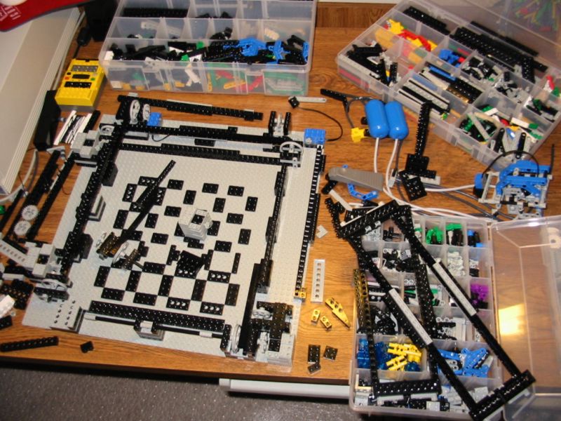
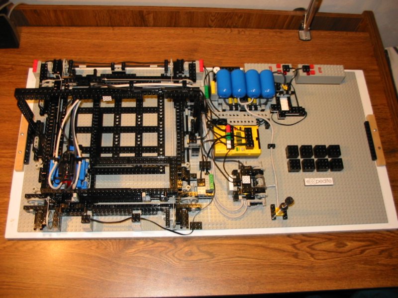
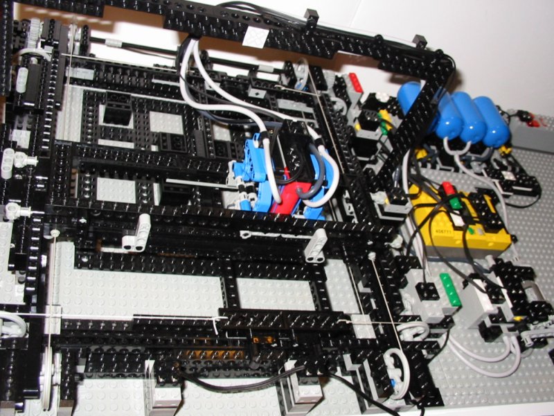
This is the biggest robot I have ever built. It just fits on a 48X48 baseplate, and all of the external subsystems (compressor, RCX, valves) are mounted on another plate. Expedite was really challenging to build, and even more challenging to program. I needed a break after this one :) |
|
I built on many of the ideas I had when testing the linear sorter. The robot is basically an x/y axis configuration with a pneumatic arm and gripper. The wiring is colour coded so you can see which motors are connected to which port on the RCX. |
|
|
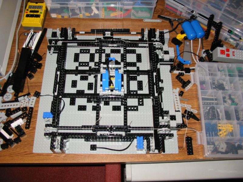
A picture in progress. This is the first time I actually thought to take a picture in the midst of the construction. Its nice to see how things started, and all the changes that were made over time. There is an early version of the pneumatic arm at the far right. This went through many revisions before I got it right. |
 |
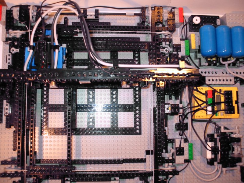
Here is the guts of the robot in testing position. The arm just sits between the two X and Y axis frames. Where the frames overlap creates a square hole for the arm to ride in. So, where ever the separate frames move, the arm slides with them. I got this idea from a joystick. Why did I use this strange configuration with string drive? I wanted the robot to be as fast as possible, so that meant the less moving weight, the better. In this configuration, none of the motors move, and the pneumatics which do move, are relatively light. |
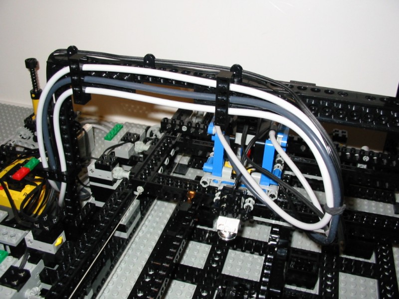 |
I mounted an overhead bar to keep the tubing and wiring neat. |
 |
Side view of the finished robot ready to go. |
Drivetrain |
|
|
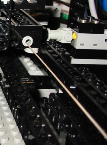
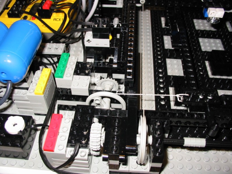
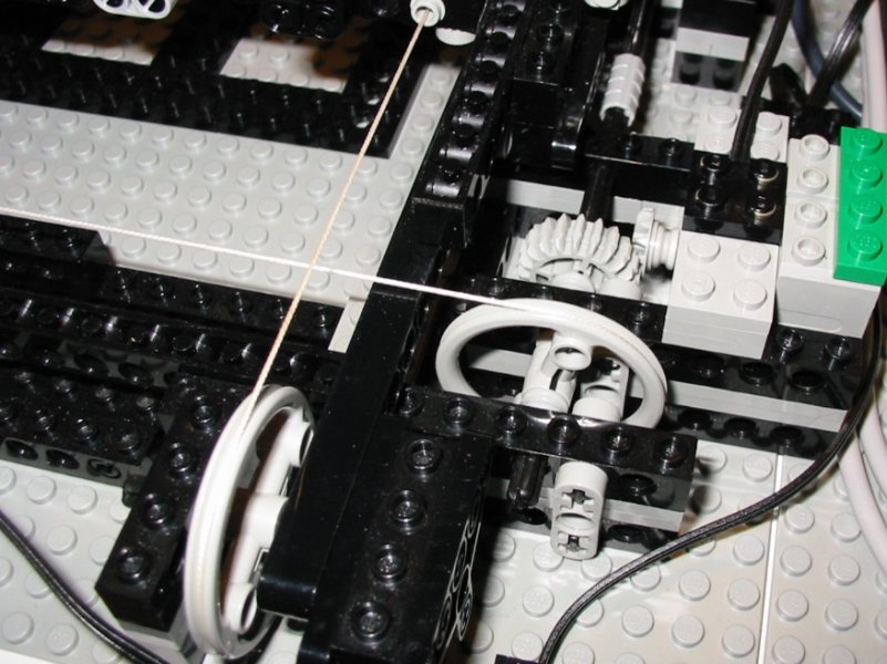
The gearing for both of the axes can be seen here, as well as the string connections to the sliding frames. Each axis was driven with two parallel motors. |
|
I originally used a standard 3:1 gear ratio (8tooth to 24tooth), and then tried to speed it up to 1:1 (16 tooth gears) once everything was working. Since the spacing is the same for these gears, the change was very simple. Unfortunately, the robot was out of control at this speed. What I ended up using is the newer double bevel gears, which give a more moderate speed increase (12tooth to 20 tooth), still in the same spacing. Gotta love those new gears! |
|
When I was first thinking about this idea, I tried out the string, and it seemed to slip on the medium and small pulleys. The large pulleys grabbed the string really well though. I think this is because the groove on these pulleys is a V shape rather than a semi circle. The pulley for the y axis is mounted higher, so the string loops pass through each other. |
Positioning |
|
|
|
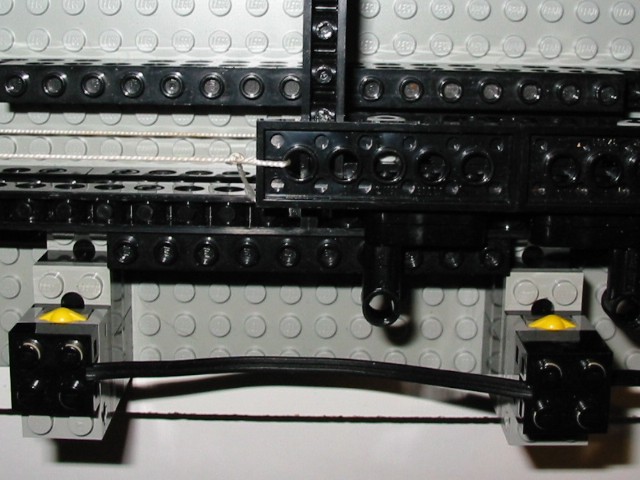
I had originally intended to use rotation sensors for the positioning, but I couldn't get the accuracy I wanted. Touch sensors provided a simple alternative. I used two sensors per axis, and two trigger points on each frame, giving four positions. I could have mounted one sensor on the frame, but I wanted to minimize the mess of moving wires. |
|
|
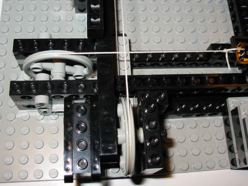
This picture shows clearly how the sensor was triggered, and how the string was attached to the upper frame. You can also see how I used an inverted beam for the frame guides. |
Gripper |
|
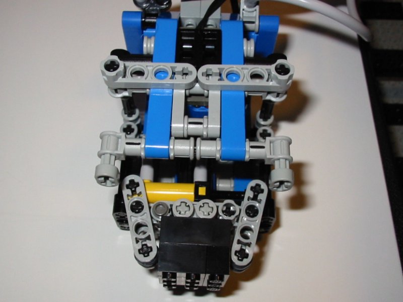 |
Close up of the arm. The gripper is shown in the lowered position holding one of the blocks. The dimensions of the blocks and game board were all specified. |
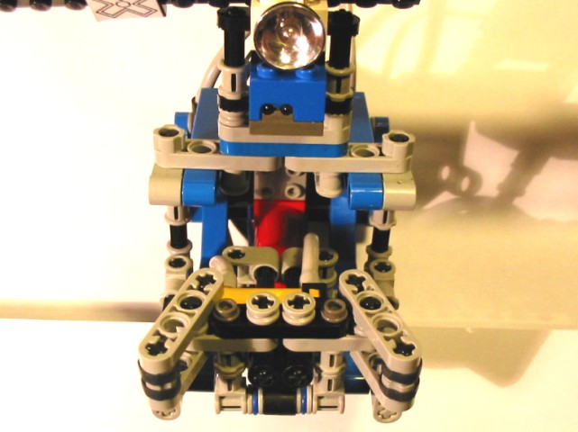 |
The final version of the arm and gripper. The red cylinder provides the lift, and the small yellow cylinder operates the gripper. The light sensor is used to scan the blocks, and the light improves the consistency of the sensor readings. |
 |
The light sensor actually scans one row ahead of the gripper. This made the program slightly more challenging. |
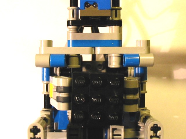 |
Underside with a block in place. |
Valves |
|
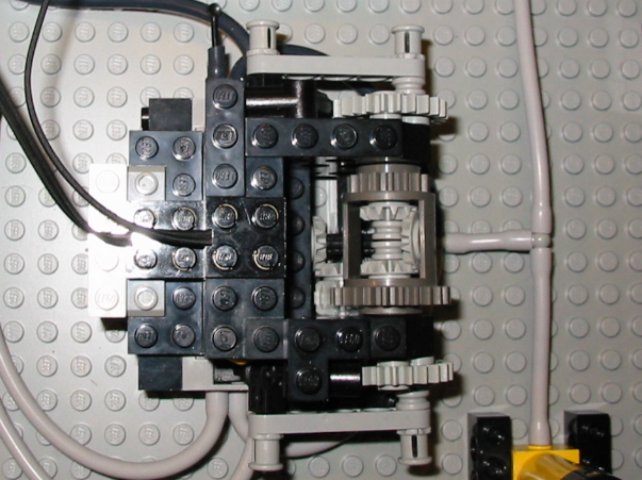 |
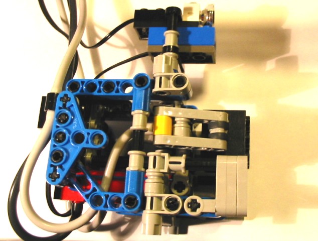
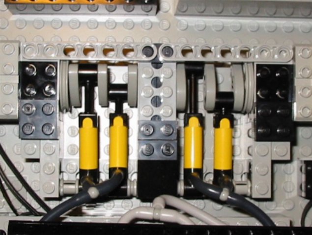
This is the same pneumatic valve switching unit (VSU) that I developed previously. It turned out to be very reliable. The light sensor for scanning the blocks was connected to the same port as the touch sensors on this unit. |
 |
This picture should make it clear how the VSU works. A crank is connected to one side of the differential, and is ratcheted so it can only turn in one direction. The crank is connected to the valve, and as it rotates, the valve cycles back and forth. The touch sensor gets triggered when the crank is halfway through the stroke for a reference point. |
 |
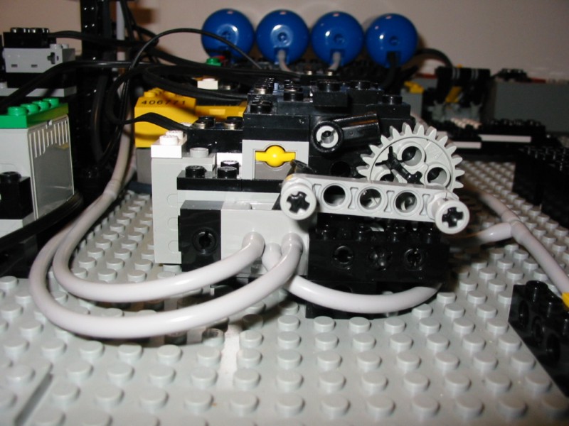
The other side of the VSU. The gearing from the motor to the crank is 1:1, so the valves flip pretty fast. some of the older valves are very stiff, and would require more gear reduction to work with this set up. |
Compressor |
|
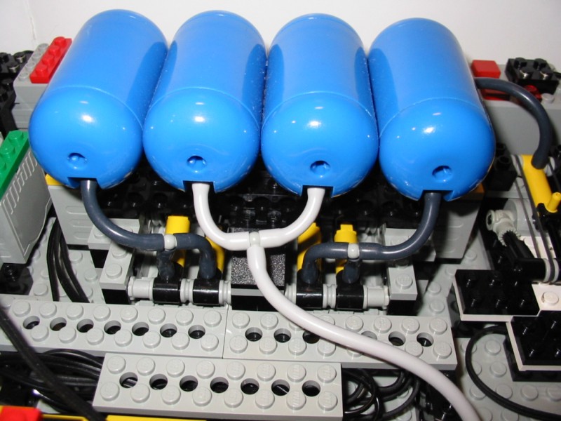 |
Monster compressor! The limiting factor for the speed of this robot was the air supply. This is because the lift arm and gripper were both pneumatic. This compressor is the end result of my search for the ideal high volume, high pressure compressor. I did not come up with this design entirely on my own, but borrowed it from Jennifer Clark. I essentially took her original design and doubled it. |
 |
What I really liked about this design is that the pumps are driven directly from the motor, avoiding nasty gear crunching sounds when the pressure gets high. Its amazing how high the pressure can get with these little pumps. If left running too long, the hose will pop off! |
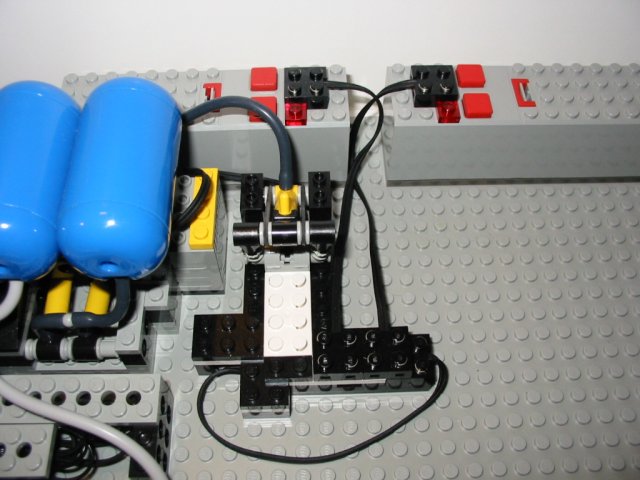 |
I was really surprised that no one asked me about this at the competition. This special configuration connects the two battery boxes in series. This was to get more speed and power out of the compressor. I purposely used old batteries in the second battery box, so the motors ran at about 11-12 volts. This was enough to get the extra power needed, but didn't damage the motors. |
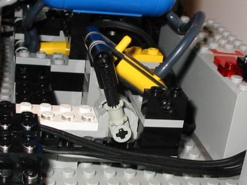 |
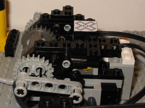
Pressure regulator. Shamelessly stolen from Sergei Egorov. When the pressure is low, the rubber bands retract the cylinder as shown, and keeps the motors turned on. |
 |
When the pressure gets high enough, the cylinder extends, and flips the polarity switch to turn the motors off. |
Well, I guess all of that work paid off. After months and months of building, programming, modifying, tweaking, etc, this robot was a very smooth and fast machine. I found that the greatest amount of time was spent in the actual picking up and putting down of the blocks. Since my gripper and lift arm were both pneumatic, I simply increased the pressure and shaved off about 5 seconds. Then, on competition day, I put in some fresh energizer titanium batteries. This shaved off another 3-4 seconds. In its prime, eXpedite could sort all eight of the blocks (the worst case scenario with no blocks in the right place to start) in about 16 seconds. Not bad considering when I first started testing it took about 30 seconds.