After completing my clinical engineering internship hours while simultaneously working on my research, followed by a three-month research sprint and thesis draft, it’s time for a catch-up post.
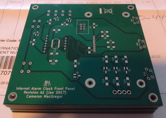
I started the ball rolling on the Internet Alarm Clock in early 2017 by designing a front panel PCB that implements the alarm clock’s physical user interface (UI).
The front panel is intended to connect to another PCB (to be designed) via a single 6 pin, 0.1″ pitch IDC connector for the I2C (data) bus, power, and button interrupt signal.
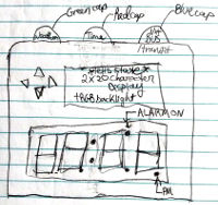
Here’s a rundown of the UI elements:
- Classic red seven-segment display for displaying the time.
- Character LCD screen for displaying additional information. Transflective with RGB backlight.
- Four directional buttons (up, down, left, right) for setting the time.
- Three buttons at the top, each colour-coded for association with a specific functionality:
- Red, associated with the clock (to match the red seven segment display)
- Green, associated with the weather reporting functionality (to match the colour of… grass I guess!)
- Blue, associated with the next arriving bus (inspired by the blue lights on TTC buses)

The front panel electronic design is fairly straightforward. An as1115 does the heavy lifting by doing three things:
- Driving the four-digit, seven-segment clock display
- Controlling the Newhaven character LCD (NHD-C0220BIZ-FS(RGB)-FBW-3VM
) backlight via three switching BJTs (to accommodate the different rated voltages of each of the red, green, and blue backlight LEDs). - Reading the button input from the seven buttons.
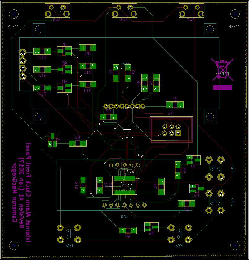
For the final layout I decided to move the up/down/left/right buttons alongside the seven-segment display, hoping to make setting the alarm (or, in the absence of Wi-Fi, setting the time) more intuitive.
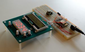
I decided to use an Adafruit ESP8266 Wi-Fi module breakout board (2471) as the Wi-Fi module, due to its wide use among hobbyists for their projects, which I can refer to for help. Adafruit’s version comes with the NodeMCU firmware, which implements a Lua-based scripting engine. As I wrote routines in Lua to exercise the displays and read the buttons on the front panel PCB via the I2C bus, I gradually built up a prototype firmware throughout 2017.
I was able to implement the following features using Lua scripting and appropriate selection of modules for a custom NodeMCU build (built using nodemcu-build.com):
- Automatic syncronization of time over Wi-Fi using NodeMCU’s Network Time Protocol (NTP) module
- Wi-Fi connection and alarm status icons
- Automatic dimming of seven segment display at night
- Setting the alarm time
- Setting date and time if no Wi-Fi found (could not fully implement due to memory constraints)
- Visual portion of the alarm, signified by colour-cycling the LCD backlight
The last feature is pretty cool:
But, after a certain point, my scripts ran out of memory. Despite there being 4 MB of flash (less 0.5 MB for the firmware) on the underlying module in which to store the scripts, it seems that the Lua interpreter has to load these text files to RAM to execute, and then the variables (of which many are strings) take additional memory, on top of the interpreter’s RAM footprint. Though I’m not entirely sure how NodeMCU partitions and manages the ESP8266 memory space, it appears that RAM is limited to the order of tens of kilobytes. So I may have to use an external microcontroller and program the user interface in C, where it can execute directly from the micro’s flash memory, and reserve the Lua scripting for the high-level network interfacing (e.g. parsing XML or JSON to get the weather and next bus).
Bill of materials, KiCad design files, and Lua scripts are available in this post’s commit.