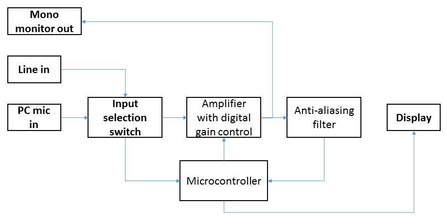
Before continuing work on the system subcomponents, I’m going to specify two basic hardware components: the microcontroller and the display.
Microcontroller
First, for the microcontroller, I will use the TIVA LaunchPad (TM4C123GXL) as the foundation on which to build the Bispectrum Visualizer. Why? It provides a fast (75 MHz) 32 bit CPU with DSP-like capability thanks to its multiply-accumulate register. It also supports in-circuit debugging via its USB interface, is supported by good software libraries and development tools, and most importantly, I already have experience with the TIVA LaunchPad. Its 32 kb of RAM is rather constrained for the matrices of values that will represent the bispectra, but this will make the firmware design more interesting as a learning experience.
The TIVA LaunchPad provides headers to connect external circuitry. My plan is to design a PCB that fits into this header that implements all of the audio circuitry, including audio connectors, amplifier, and filter.
The board runs from a 3.3 V regulated supply that can drive up to 500 mA with overcurrent protection, powered by 5 V from a micro USB connection. This means the ADC of the onboard microcontroller will be able to digitize voltages in the range of 0 to 3.3 V – important to know when designing the amplifier and filter electronics.
Display
And finally, for the display, I will use an existing display module already designed to connect to the TIVA LaunchPad, the Kentec QVGA Display BoosterPack (BOOSTXL-K350QVG-S1). Specifying this display now is important because it will define which header pins are free to use for my own circuit.
